Gas Dispersion Analysis and Explosion Protection of a Gas Turbine
Gas Turbine | Grid Generation | Marine Application | Turbomachinery
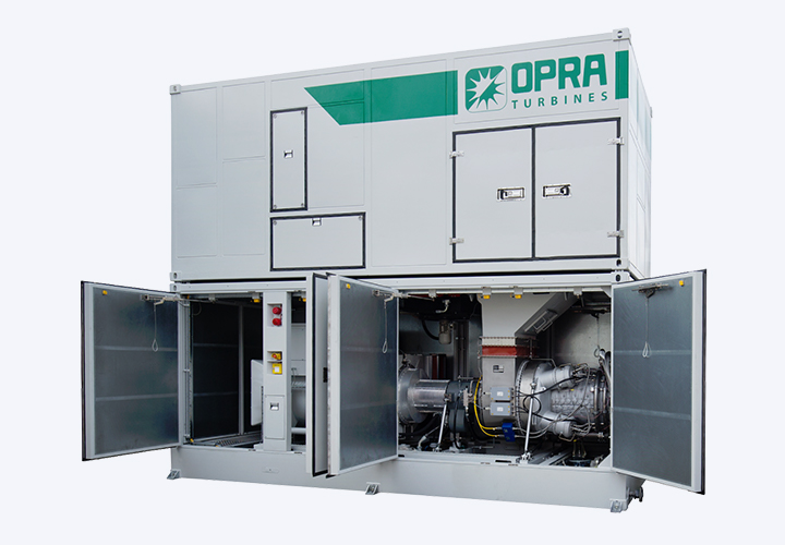
OPRA Turbines develops, manufactures, markets, and maintains generator sets using the OP16 series of gas turbines, which is rated at 1.85 MWe. Different combustion systems can be mounted on the OP16 gas turbine depending on the application and requirements. The gas turbine generator set comes in a containerized package (shown in Figure 1), including the OP16 gas turbine, fuel systems, generator, control system, air intake, and ventilation system.
CFD simulations are an integral part of OPRA’s design process. Simulations are used to analyze and optimize flow within various areas, including combustion, turbomachinery, and gas dispersion analysis. OPRA has been exploring using the open-source software package OpenFOAM to complement commercial CFD software packages. A good mesh is essential for performing a CFD analysis, and OpenFOAM benefits from hex-dominant meshes. Various open-source meshing tools are available for OpenFOAM, which generally work fine for simple geometries. However, these meshing tools are hard to use for real (industrial) geometries because of limited geometry import, non-intuitive operation, and limited documentation.
“The Fidelity Automesh meshing tools are OPRA’s preferred solution because of the full -hex and hex-hybrid meshes, automatic meshing and direct export to OpenFOAM.”

Figure 2: CFD simulation process at OPRA
Cadence’s meshing suite has been implemented in OPRA’s design and CFD methodology, as shown schematically in Figure 2. These meshing tools are a preferred solution for OPRA because of the full-hex and hex-hybrid meshes, automatic meshing, and direct export to OpenFOAM. Fidelity Hexpress is used for combustion and gas dispersion analysis and Fidelity Autogrid for turbomachinery.
The following case study shows the use of Fidelity Automesh for CFD simulation.
Project Description
OPRA has developed a marine version of its OP16 gen-set for onboard ships. As part of this project, a gas dispersion analysis of the OP16 marine package has been performed. The OP16 marine gen-set will operate on a range of fuels with significantly varying gas composition and energy density. Enclosures, including gas systems, should be ensured of explosion protection in case of gas leakages as the enclosure ventilation air and the gas mixture may form LEL (Low Explosion Limit) volume clouds which may ignite in the presence of an ignition source. To ensure a non-hazardous atmosphere inside the enclosure, gas detectors must be placed at the right locations to identify the eventual leakages. As part of this enclosure gas dispersion analysis, a CFD study has been carried out to investigate the ventilation flow behavior inside the package and the behavior of the LEL volume clouds due to gas leakages.
The gas leakages considered in the CFD study are tiny leakages that can occur at the flanges, fittings, or small cracks in the pipeline. Possible leakage locations in the gas systems are identified to perform the gas dispersion analysis, and small leakages are simulated at these locations. The CFD simulation is carried out in two steps: firstly, the flow simulation is carried out where the leaked gas flow will mix with the air at specified boundary conditions. The second simulation is carried out to capture the LEL volume clouds. The latter simulation is performed based on the passive scalar approach.
“A good mesh is one of the fundamentals to run the CFD analysis successfully. A complicated geometry is easily meshed by Fidelity Automesh and delivers a very fine mesh. As many features are automated, it saves the user a significant amount of time to generate the mesh. Furthermore, any small changes made to the geometry in CAD can be easily modified in Fidelity Automesh.”
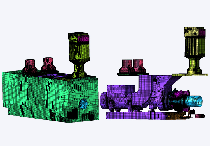
A good mesh is one of the fundamentals of running the CFD analysis successfully. The Fidelity Automesh meshing tool is used to mesh this marine package. The package has a complicated geometry, including thin, small surfaces, small holes, and narrow pipelines. A complex geometry like this is easily meshed by Fidelity Automesh and delivers a very fine mesh. As many features are automated, it saves the user significant time to generate the mesh.
Furthermore, any small changes made to the geometry in CAD can be easily modified. This feature helped us to generate the mesh for different leakage sizes quickly. Figure 3 shows the mesh created for one of the gas leakages.
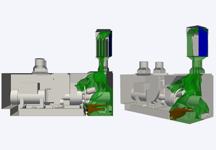
Figure 4 shows the LEL volume clouds of one of the leakages obtained from the CFD analysis. The LEL volume clouds shown in red represent the 100% LEL volume clouds, and the volume clouds shown in green represent the volume clouds that the gas detector set point will detect. Based on the volume clouds required for the gas detector set point (shown in green), the locations of the gas detectors are defined. In case of any gas leakages in the enclosure, the gas detectors placed in these locations ensure that the leakages are detected.
“Cadence’s meshing suite significantly reduced our meshing time and improved the mesh quality resulting in better CFD simulations.”
Authors
Darsini Kathirgamanathan, Gas Turbine Performance Engineer – OPRA Turbines International BV
Thijs Bouten, Principal Combustion Engineer – OPRA Turbines International BV