Toyota Motorsports: Optimization of a Turbocharger Compressor for Motorsport Applications
Automotive | Turbomachinery | Optimisation | Compressor | Turbocharger
Challenges
TOYOTA Motorsports is a high-performance testing and development facility located in the centre of Europe, in Cologne, Germany. One focus is on chassis and engine design for automotive and motorsports. Specialising this high technology developments for motor sport engines the existing turbocharger components already show a high-performance level. Hence, further improvement by traditional means, i.e. classical trial-and error procedures are hardly compatible with the required turn-around times of a modern design environment. Numerical optimisation processes allows to explore many designs in an automatic way, thus, the developer has the opportunity to evaluate many more designs compared to what could be achieved manually.
Aside from an increasing engineering complexity, another challenge is that compressor impellers already work very close to the structure-mechanical limits of the material. Most changes in shape immediately lead to an exceeding of the acceptable stress level. An optimisation under exclusive consideration of the aerodynamic behaviour does not guarantee that the resulting optimal design is structurally feasible. Thus, simultaneous optimisation including aerodynamic and structural forces is necessary. This is referred to as multi-disciplinary optimisation coupling Computational Fluid Dynamic (CFD) with Computational Structural Mechanic (CSM) simulations.
Optimisation Targets & Workflow
In the present project, the characteristics of a centrifugal compressor for an exhaust gas turbocharger are optimised by a multidisciplinary coupled CFD-CSM optimisation. The considered compressor stage consists of a radial impeller with six main and six splitter blades with a vaneless diffuser (Figure 1). Two aero-thermodynamic objectives and one structure-mechanical as well as two aerodynamic constraints are considered:
1) Increase of isentropic efficiency
2) Same, or higher absolute total pressure ratio
3) Same choke mass flow as original geometry
4) Extension of operating range towards stall margin
5) Maximum von Mises stress are below limit
The objectives listed above require simultaneous optimisation at four operating points: design point (target 1, 2, 5), two operating points close to the stall (target 4) and one point at the choke (target 3).
Coupled CFD-CSM Workflow with FINE™/Design3D
To satisfy the mechanical and aero-thermodynamic objectives and constraints, the CFD and CSM simulations are jointly integrated into one optimisation workflow (Figure 3). Each new design is first checked structurally by the CSM solver. Only if the von Mises stresses do not exceed the specified maximum value, this new design will be computed via CFD and included in the optimisation. Since the computational time for CFD is much higher than the one for a CSM simulation (approx. 2 min), a lot of effort can be saved if a design does not fulfil the structural constraints. However, structurally unacceptable designs are fed into the learning database in order to drive the optimiser.
Parameterisation
The domains for the CFD and CSM simulations are parameterised in AutoBlade™. 154 parameters define impeller, meridional channel and solid body. To avoid a huge number of structural-mechanical non-feasible designs it is decided to keep the hub shell of the base design. Therefore, the parameters, which define the hub shell of the impeller, are not modified during the optimisation. To further reduce the number of free parameters, the thickness distribution along the camber curve is not modified. In total 33 parameters are considered as design variables for the optimisation for example shape of the hub and shroud, the camber curves as well as the meridional and tangential blade position.
Meshing
For the automated optimisation workflow, it is important to have a robust setup for the mesh generation. Depending on the ranges of the modified geometry parameters, new designs can significantly differ from the original design. The mesh set up has to be robust in order to avoid mesh and simulation failures due to insufficient grid generation. Therefore, NUMECA’s robust and fully automated meshing tool OMNIS™/AutoGrid is used for the fluid domain. Mesh independence is ensured by a mesh convergence study with three different mesh resolutions (1, 2 & 3 million points). Based on this investigation, the 2 million-point structured multi-block mesh is chosen for the optimisation. To check if the high mesh quality is also ensured for the whole design space, additional to the grid convergence study the robustness test is performed. Therefor hundreds of randomly generated geometries covering the whole range of the design space are meshed automatically. In this check all geometries were successfully mesh and the orthogonality was for no design below 20°.
Optimisation & Results
In order to obtain a meaningful database for the start of the optimisation, a minimum of three times the number of samples in relation to the free parameters are needed. In the present case with 33 free parameters, hence at least 100 samples would be necessary. However, more samples were computed as it was decided to test several database generation strategies e.g. Latin Hypercube. In total four databases were generated parallel in one and a half day. For the optimisation all databases are combined. Out of 292 database designs 270 samples met all quality criteria in terms of mesh and convergence quality, so that a more than adequate database was available at the start of the optimisation.
During the optimisation each new design is added to the initial database. Thus, the database is enriched in the vicinity of the expected optimum. It is recognised during the optimisation run that not all objectives are properly achieved. Hence, the optimisation is stopped, and the priorities of the different optimisation goals were adapted. After the modification a new optimisation run is started. In this simulation run some parameter bounds were reached. Hence the optimisation is stopped and restarted after the widening of the parameter ranges a new optimisation is started. This procedure of repeated adaptions during the optimisation has proven to be useful, since – a priori – the priority of individual objectives can only be determined very vaguely.
Results
Figure 4 summarises the results at best point (OP2) of databases and optimisation runs for the isentropic efficiency and the total pressure rise.
All designs within the red area of Figure 4 show both an increase in the total pressure and efficiency. The initial design is in the lower-left corner of this box. The two best designs D1 yellow and D1 green are compared with each other and the original design. These two designs both fulfill all optimisation goals and show substantial improvements. By the selection of the designs not only efficiency increase and total pressure ratio are considered, but also the new operating range and the structure -mechanical results are taken into account. Figure 5 shows the geometrical differences between the selected optimal design and the original design. For the aero-thermodynamic optimisation goals the performances relative to the original design is listed with each design.
For the two selected geometries the complete speed line is simulated (Figure 6). Design D1 shows an increase in the total pressure ratio of up to 8.0% relative to the original design with a simultaneous expansion of the stall margin. In addition to the extension of the operating range, the most noteworthy improvement is the positive slope of the speed line close to stall, which, in contrast to the original design, ensures stable operation even in the immediate vicinity of the surge line. All chosen designs maintain the minimum choke mass flow. The efficiency is increased by 1.1 percent. The design with the highest pressure ratio increase also provides the highest efficiency gain.
D1 shows an efficiency increase of 1.4 % relative to the. In contrast, D2 has slightly lower overall pressure ratio and efficiency improvements but features an extended surge limit compared to D1. This is a classical conflict of multi-objective optimisation, where different goals can sometimes act in opposite directions. The final decision is up to the user.
The von Mises stresses in design D1 exceed the maximum permitted limits by approximately 3%, which is still within the tolerance limit. Figure 7 shows the increased stresses along the blade leading edge compared to the initial design. The areas of higher stresses have grown, but the peak value remains within the tolerance limits.
Conclusions
The presented multidisciplinary CFD-CSM centrifugal compressor optimisation is successful and all aerodynamic targets are fulfilled. The structural integrity is also ensured. The results of the optimisation are very satisfactory:
- Efficiency increase by up to 1.4% (percentage points)
- Up to 8.0% higher total pressure ratio
- Maintaining the chocking mass flow
- Extension of the surge line up to 5%
- Von Mises stresses are below limit
Author
Kathrin Wendl, NUMECA Ingenieurbüro
Products
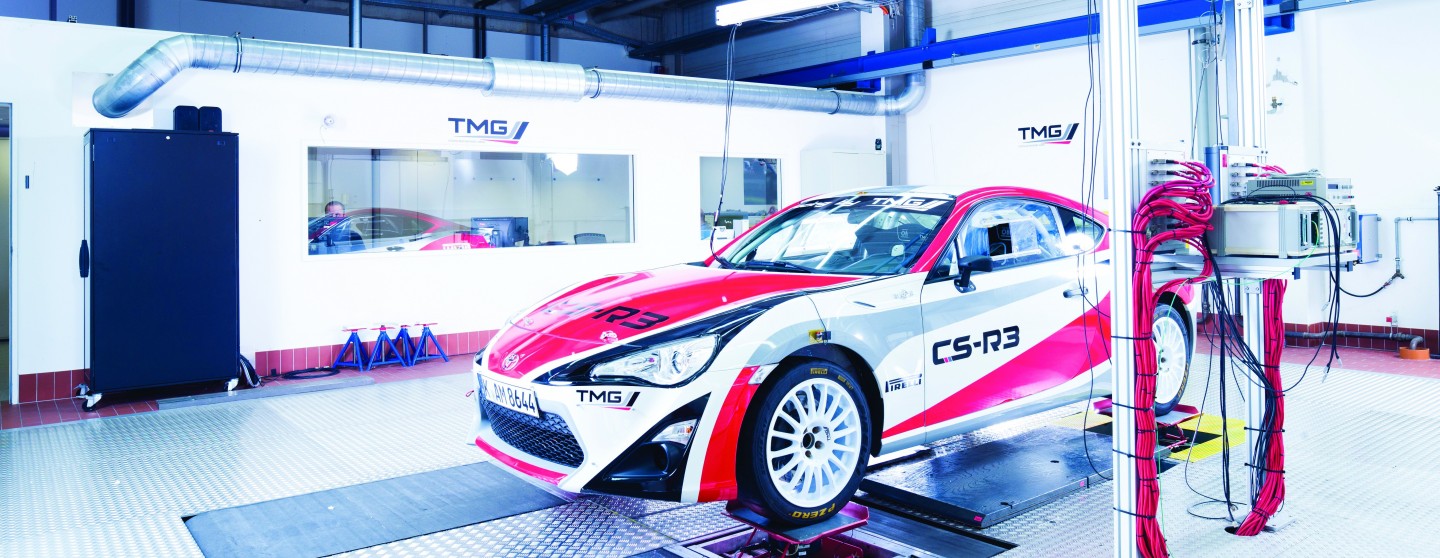 TOYOTA Race Car
 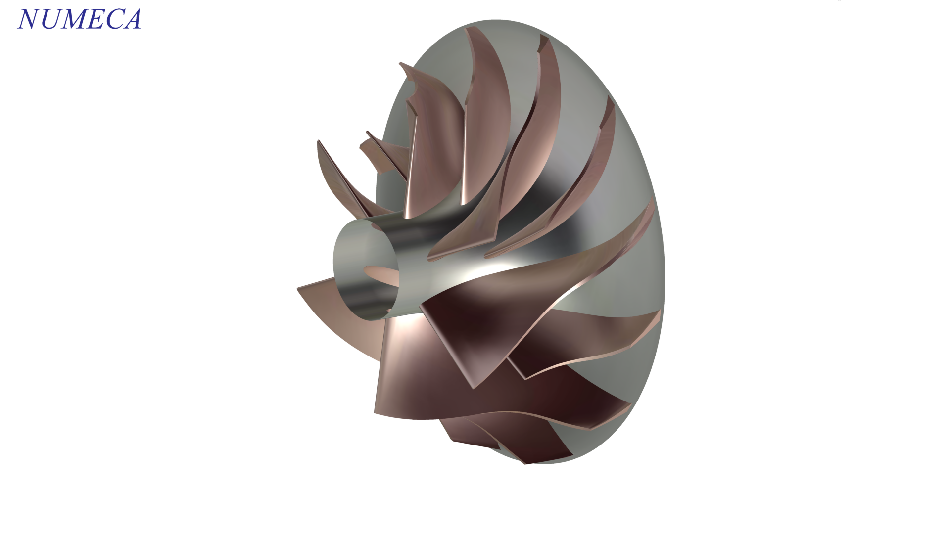 Figure 1 Compressor Base Design
 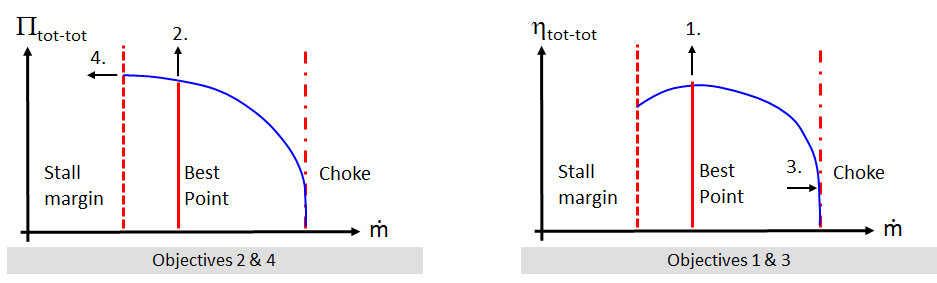 Figure 2 Schematic representation of the optimisation goals
 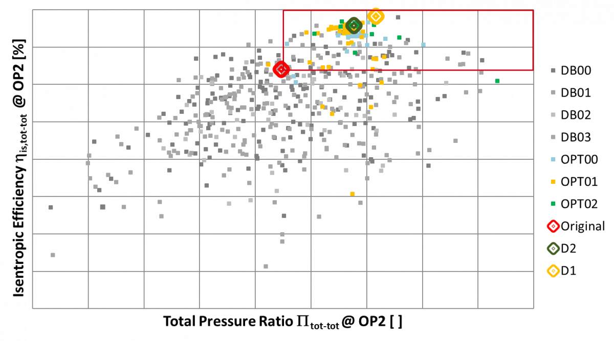 Figure 4 Result from database & optimisation isentropic efficiency over total pressur
 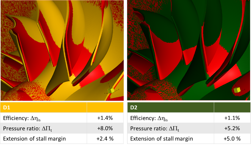 Figure 5 Comparison of original geometry and selected designs D1 and D2
 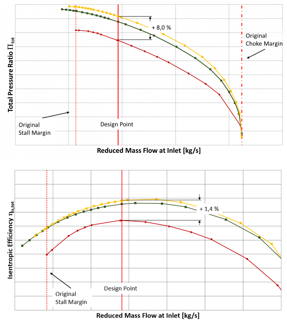 Figure 6 Speed lines of designs D1 (yellow) & D2 (green) compared with original design (red)
 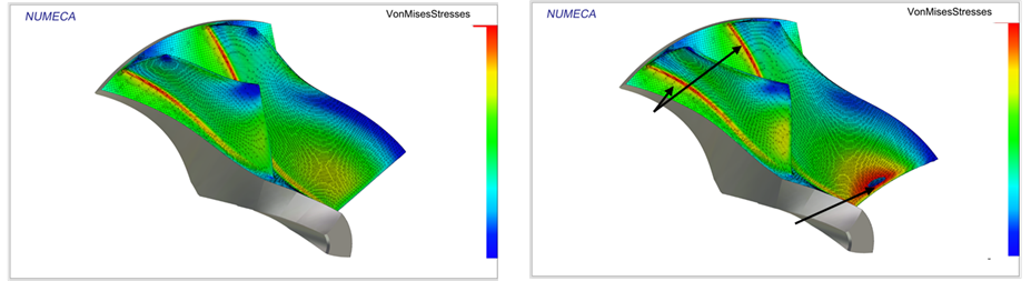 Figure 7 Comparison von mises stresses original design (left) and D1 (right)