Full-scale CFD Simulations of the SA Agulhas II
Marine
The Sound and Vibration Group (SVRG) at Stellenbosch University is investigating the seakeeping of the SA Agulhas II (SAAII, Figure 1), South Africa’s polar research and supply vessel, owned by the South African Department of Environment, Forestry and Fisheries. She was manufactured by STX Finland in Rauma shipyard, measures 121.3 m between perpendiculars and is 21.7 m wide. She is propelled by four Wärtsilä 3 MW diesel generators that power two Conver Team electric motors which are each connected to a shaft with a variable pitch propeller. Accommodations are available for 44 crew and 100 passengers on annual research and re-supply voyages to Antarctica, Gough Island and Marion Island (Figure 2).
This work will use the CFD capabilities of NUMECA’s FINE™/Marine to determine calm water resistance, added resistance due to waves and motion responses of the vessel, all performed in full scale.
The SVRG uses NUMECA’s FINE™/Marine software package to conduct the CFD study. It offers a seamless workflow, from mesh generation to postprocessing. The geometry and the surface mesh of the SAA II is shown in Figure 3 and Figure 4. An unstructured fully hexahedral mesh with anisotropic cell refinement is used, to ensure both a high-quality grid as well as high control over cells distribution. The inflation technique in HEXPRESS™ allows to insert the near wall cells for an accurate resolution in the boundary layer, keeping both the first cell size (important for turbulence modelling, here using a wall function) and ensuring a smooth transition into the Euler mesh.
The setup of the CFD chain is greatly simplified using the C-Wizard: this tool takes engineering data as input, e.g. drafts, speeds and sea conditions, and provides the full setup from meshing to pre-processing. However, everything can be adapted according to the user’s likings and preferences, making it an ideal tool to get started fast, but also provides full access to the flow solver and numerical details. This is of course important for an academic usage of an industrial code.
Some of the results are depicted below, for the design draft conditions and a vessel speed of 12 kn. Figure 7 shows the wetted surface for a calm water simulation, totalling to 1671 m2 and also indicating some bow spray. In this lowest form of life simulation the grid resolution is kept on the low side, the thickness of the transition zone water to air is directly linked to the mesh cell sizes, as can also be taken from Figure 7.
Accuracy and grid density were however greatly increased in the full unsteady simulations for seakeeping: shown are results for a wave length of 126 m, leading to a wave period of 9 s and an encounter period of 6.3 s, the wave height is 1.6 m. These conditions are quite common during the voyages if the SAA II. The wave patterns are given in Figure 5 and Figure 6: a correct convection of the waves through the domain can be observed, as well as non-linear interactions between the incoming waves and the bow and stern flow patterns. The vessel motions for heave and pitch are shown in Figure 8 and Figure 9, for a total simulation time of 100 s. Although these are regular waves, an out-of-phase response is already observed. This will be investigated in much more detail in the upcoming work, where appendages, irregular sea spectra will be implemented, as well as the rough sea conditions in the the SAA II is operating.
Products
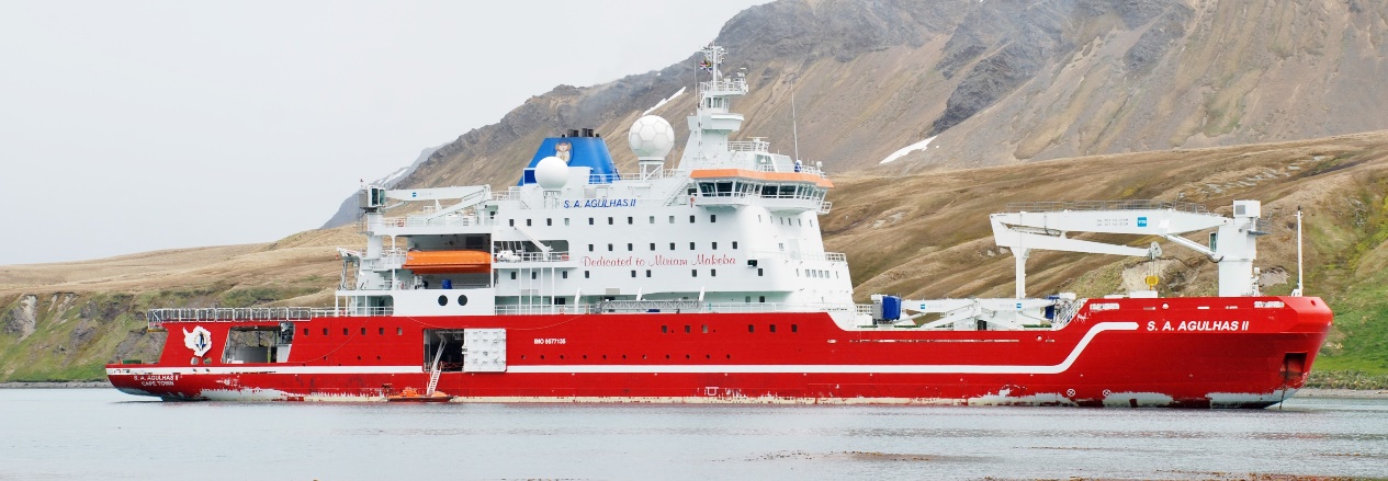 Figure 1: SAA II vessel during the 2015/2016 relief voyage Antarctica.
 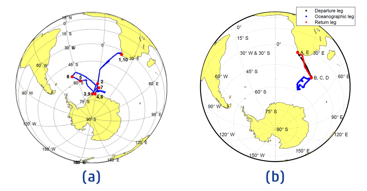 Figure 2: GPS tracks for an (a) Antarctic relief voyage and a (b) Marion Island voyage of the SAA II.
 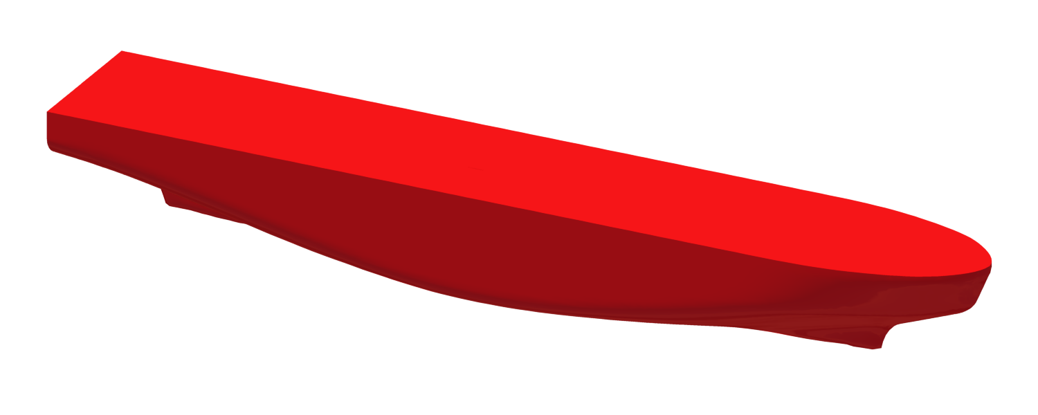 Figure 3: Geometry of the SAA II
 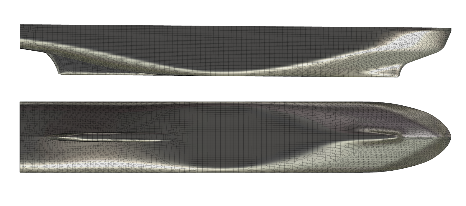 Figure 4: Surface mesh of the SAA II
 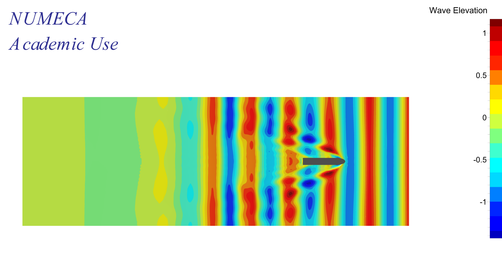 Figure 5: Top view of the in wave elevation
 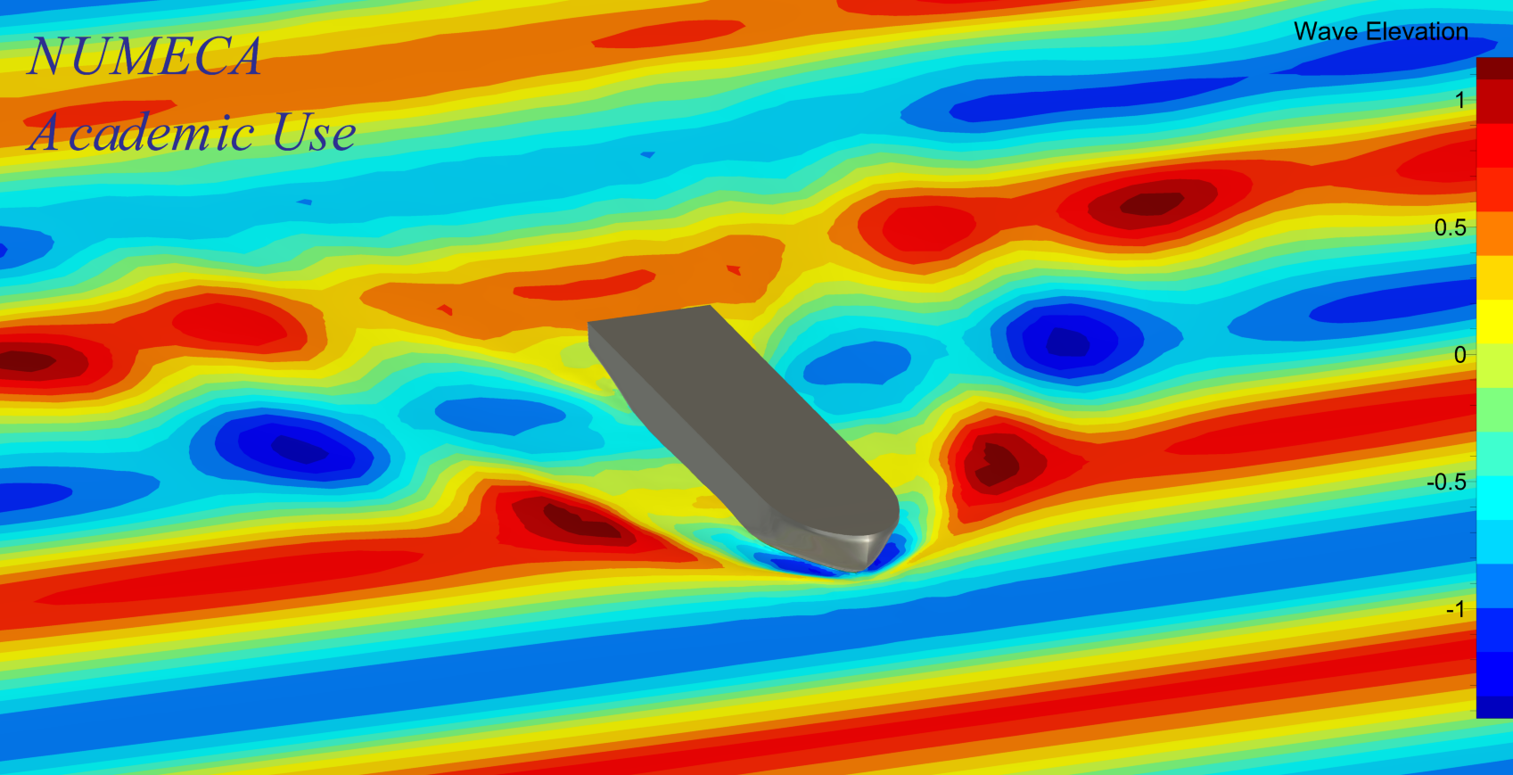 Figure 6: Travelling shot of the SAA II at 12 kn
 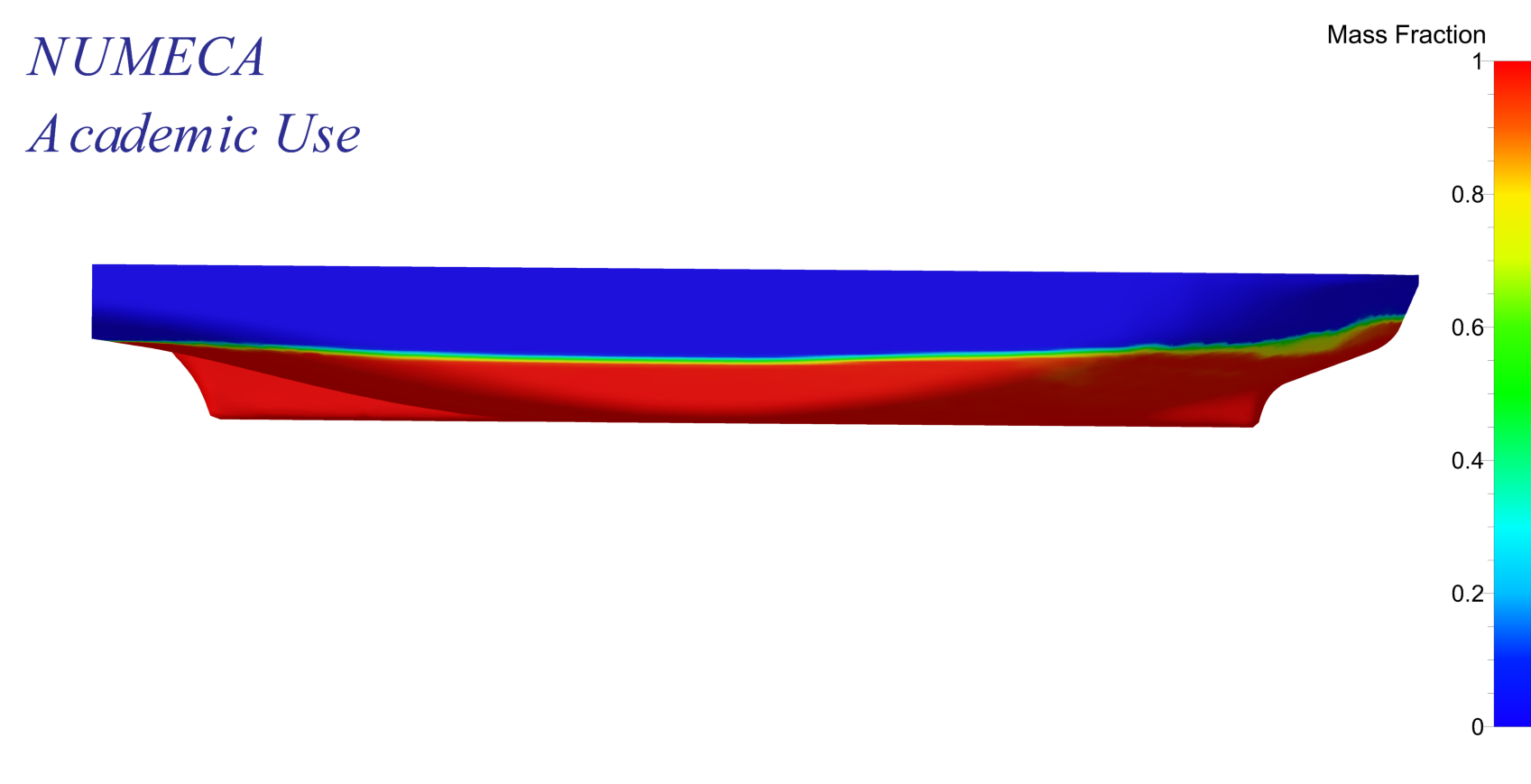 Figure 7: The calculated wetted surface area, 1671 m^2
 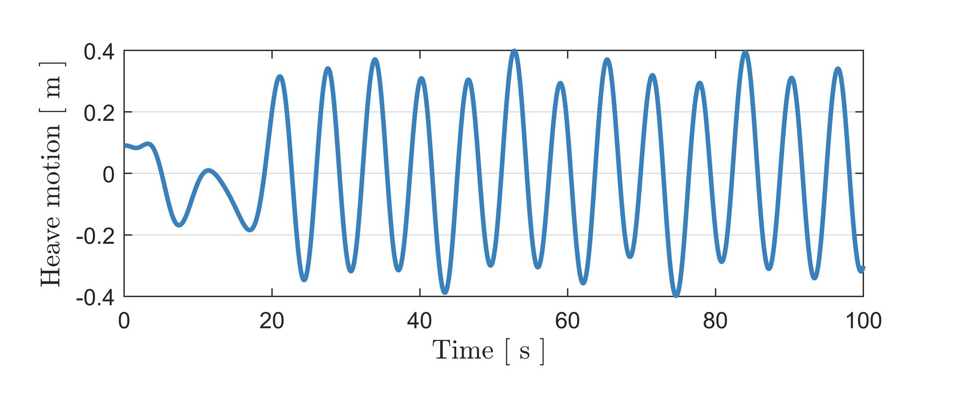 Figure 8: Heave motion
 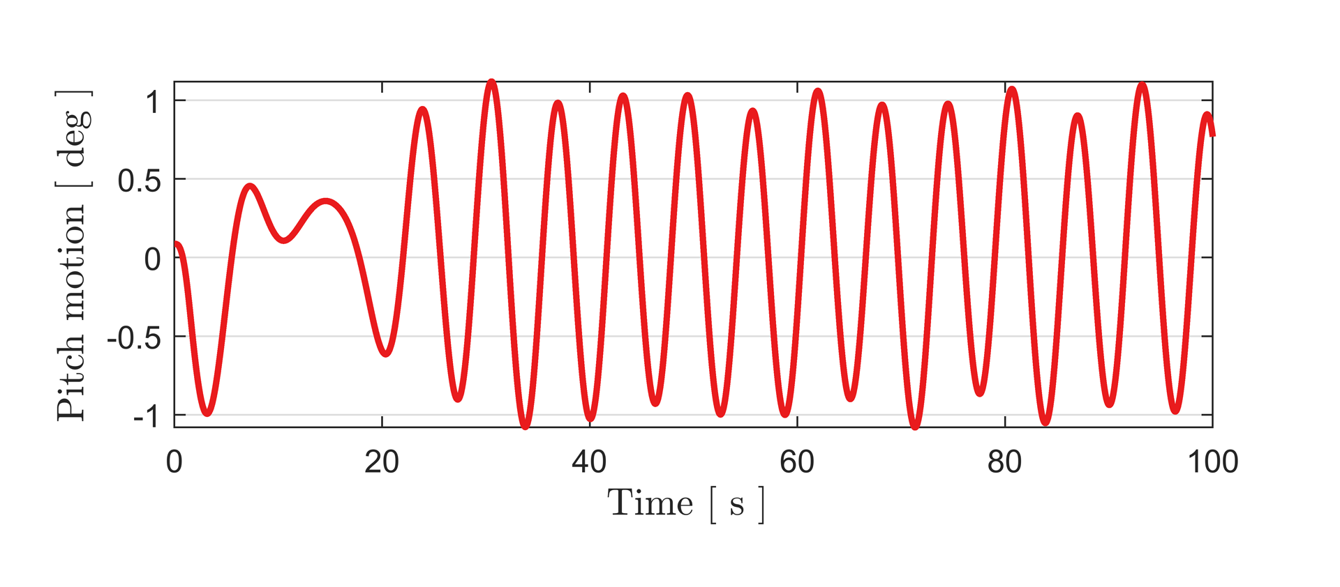 Figure 9: Pitch motion