Extending quadcopter drone flight time and range with OMNIS™ CFD simulation
NLH Simulation| Drone | Quadcopter | Flight Conditions | Propeller | External Aero | Optimisation
Drones have proven to be an efficient solution for a large range of applications within the military, industrial, and private consumer domains. In the past decade, their use has been soaring and their annual growth rate is anticipated to exceed 50% [1].
There are two main categories of aerial drones: rotorcraft capable of vertical take-off and landing (VTOLs) and fixed-wing vehicles. Rotorcraft drones offer important advantages over the fixed-wing systems, such as their ability to hover (maintain a constant altitude) and the fact that they are easier to control and operate. This makes them particularly suitable for unique applications like indoors operations, maneuvering in wind turbines and construction site inspections to name a few. On the other hand, multicopters also have inherent shortcomings, the most important one being their limited flight time and range. Even modern and innovative electric drones have a limited flight time of around 20-30 minutes depending on flight conditions. Only very few conventional electric multicopter drones in the high-end class, can reach flight times close to 1 hour. The application of Computer-Aided Engineering (CAE) techniques and Computational Fluid Dynamics (CFD) in particular can help to significantly improve the efficiency of drones and extend their flight time and range.
NUMECA’s fully integrated multiphysics CFD environment OMNIS™ paves the way for faster, more accurate quadcopter simulations, combining structured and unstructured meshing solutions with the fastest CFD solvers on the market within one platform. Its Nonlinear Harmonic model (NLH) has proven to be a cost-effective solution for unsteady simulations up to two orders of magnitude faster than the conventional methods. The case study presented in this article demonstrates the aerodynamic simulation and optimisation of an industrial quadcopter drone in hover mode, the most energy intensive mode of this type of drone.
Geometry
The studied geometry (Figure 1) corresponds to the most widely used rotorcraft drone configuration today: the quadcopter geometry. The model used here was provided by the authors of [4]. Drone manufacturers for the private consumer sector (amateur video shooting, racing drones, drones for kids, etc) predominantly rely on this type of configuration.
The propeller blade (Figure 2) was modelled with NUMECA parametric modelers, taking into account the required thrust. Multiple sections were extracted from the original geometry and stacked together in order to build the 3D blade. An appropriate twist distribution was provided to make sure the parametrised blade resembled the original geometry as close as possible.
The setup benefited from the symmetry of this drone geometry: only one-fourth of the drone needed to be included in the computational domain, hence only one arm. The chosen domain definition represented a practical case, corresponding to “free air” simulation at a hovering altitude that is high enough to neglect any ground effect.
Meshing
Due to the complexity of the drone domain, an automatic unstructured mesh was generated using Hexpress (Figure 4). Hexpress automatically refines the mesh near high curvature areas and edges, thus minimising user interaction and engineering time. This leads to a high-quality mesh, sufficiently robust to be used for an optimisation.
One blade of the propeller was meshed using multiblock structured mesh generator AutoGrid (Figure 5). AutoGrid uses a wizard-type approach for meshing various types of turbomachinery configurations with different characteristics, such as centrifugal pumps, axial compressors, etc. This approach makes it very easy and fast to generate a high-quality structured mesh with multiple grid levels. A variable tip gap was applied to the blade. Also, a matching periodic connection between two periodic faces was automatically ensured and computed. Meshing only one blade, combined with such a matching connection, led to a two-fold cell count reduction with the corresponding simulation speed-up.
Both meshes were then assembled together and a rotor-stator interface was set up between the two domains. It is worth noting that OMNIS™ allows the user to combine and run structured and unstructured meshes in the same computation, taking advantage of the intrinsic speed advantage of using structured meshes and of the robustness of the unstructured ones. This also reduces RAM and disk consumption. The approach does not require tuning any solver settings.
Simulation
Open is capable of both steady and unsteady Non-Linear Harmonic (NLH) [5] simulations. The propeller was set to rotate at 5,000 RPM, whereas the drone arm is stationary. The Spalart–Allmaras model was used to predict turbulence in the flow. For the steady simulation, a mixing-plane interface was used, while for the NLH simulation, a specific treatment based on Fourier decomposition was applied. This provides the benefits of a domain scaling approach with a computational cost similar to that of the mixing plane.
The Non-Linear Harmonic method provides unsteady flow results with considerably less constraints than the domain scaling and phase-lagged methods. For this project, one harmonic per domain was added to capture the unsteady perturbation in the domain.
Comparison of the results (Figure 6 and 7) obtained in the framework of steady and unsteady simulation, revealed the presence of strong unsteady features in the flowfield. The pressure distribution on the airframe was largely impacted by the instantaneous position of the propeller. The velocity field around the drone was subject to strong periodic oscillations linked to the rotor rotation. The results comparison shows that steady simulation can provide sufficient representation of the mean flow field. However, the NLH analysis provides accurate information on the unsteadiness of the flow field, offering a large scope of valuable data for an engineer in terms of unsteady flow physics, blade and airframe loading, as well as blade tip vortex and bluff body recirculation dynamics, at a cost comparable to a steady simulation.
Drone Design Optimisation
NUMECA software offers multiple possibilities for design parametrisation and optimisation. The available optimisation methods range from single-objective optimisation to multi-objective and robust design optimisation (RDO) that takes into account operational and manufacturing uncertainties. A drone optimisation process can benefit from all these methods. The final choice of the technique depends mainly on the expected operation modes.
Figure 8 represent an example of geometry parametrisation and its variation in the framework of the optimisation study. The propeller geometry used for the optimisation study was parameterised on CAD model level. The angle of attack of the propeller at 3 spanwise sections was taken as the design variable. Each geometry was automatically re-meshed in AutoGrid. The drone arm was parameterised using 3 morphing vectors placed in the geometry. They allow the optimiser to optimise the shape of the drone using the morphing technique, while also satisfying multiple constraints that are applied to ensure feasible designs.
NUMECAS’s optimisation routines are based on gradient-free algorithms that are considered to be much more efficient than gradient-based optimisation for complex multi-component systems such as drones. The employed optimisation processes benefit from a great speed-up thanks to the use of built-in surrogate models or artificial neural networks. Underlying evolutionary and genetic algorithms ensure an optimum converged solution in terms of defined objectives, such as flight time maximisation. Practical use of such algorithms confirms that it can lead to novel, innovative, and sometimes even unexpected optimum system designs.
Summary
Simulation technologies have become a key element of drone design. The rapidly growing and highly competitive market, drives commercial drone manufacturers to improve efficiency and expand the flight envelope and range of their applications. Maximum flight time and range remain to be one of the most important issues to address for multicopter electric drones. NUMECA’s CAE suite, with OMNIS™ at its core, offers an efficient and cost-effective solution for the simulation and optimisation of drones.
The presented case study demonstrates a set of powerful capabilities, such as the combination of structured and unstructured meshing techniques and high-fidelity unsteady simulations using the Nonlinear Harmonic Method. Fully automated optimisation, based on efficient evolutionary algorithms, parameterisation and morphing, ensure a fast and robust workflow and an optimum design result for the defined objectives, such as maximising flight time and range.
Click herefor a full white paper download about this case.
References
[1] Commercial Drone Market Size, Share & Trends Analysis Report By Application (Filming & Photography, Inspection & Maintenance), By Product (Fixed-wing, Rotary Blade Hybrid), By End Use, And Segment Forecasts, 2019 – 2025. Jun, 2019. URL: https://www.researchandmarkets.com/reports/4827913/commercial-drone-market-size-share-and-trends. Accessed 10 May 2021
[2] Unmanned Aircraft Systems & Advanced Air Mobility. URL: https://aviationplanning.design.blog/unmanned-aircraft-systems/. Accessed 10 May 2021
[3] DJI FPV – Specs. URL: https://www.dji.com/be/dji-fpv/specs. Accessed 10 May 2021
[4] The quadcopter geometry was described in the paper “Weerasinghe S.R. and Monasor M., Simulation and experimental analysis of hovering and flight of a quadrotor, 13th International Conference on Heat Transfer, Fluid Mechanics and Thermodynamics (HEFAT 2017), Spain 2017” and was kindly provided by its authors. The CAD model was generated by Miguel Monasor Pascual, Mechanical and Aerospace Engineer. Compared to the provided geometry, a new propeller geometry was generated and is retained for the study.
[5] Vilmin S., Lorrain E., Hirsch C., Swoboda M., Unsteady Flow Modeling Across The Rotor/Stator Interface Using The Nonlinear Harmonic Method, ASME Paper, GT-2006-90210, 2006
Products
 Coverphoto by asoggetti on Unsplash
 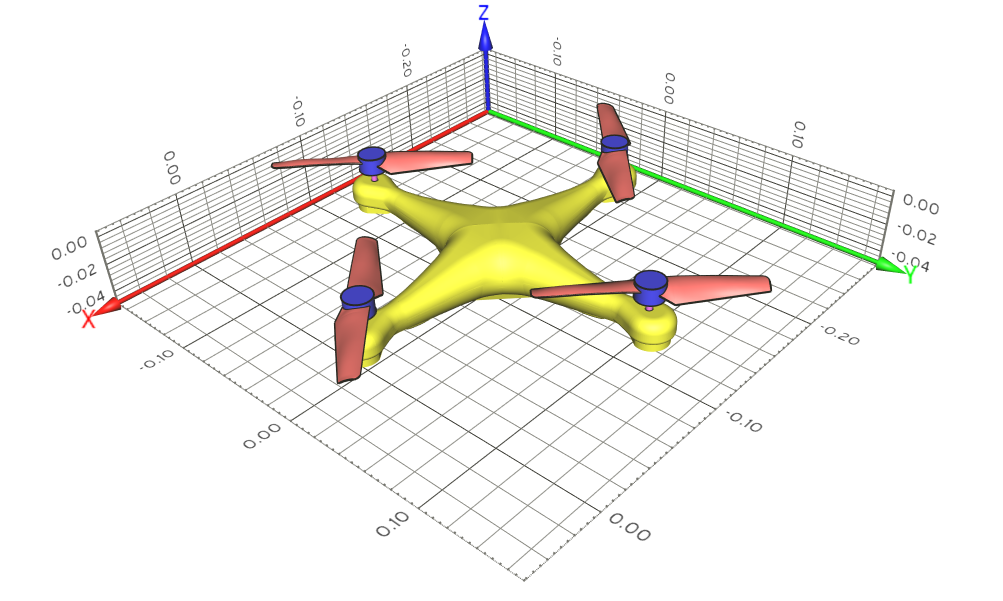 The considered drone geometry and its dimensions. The drone CAD files are provided by Mr. Monasor and Dr. Weerasinghe, University of the West of England.
  Geometry and domain
 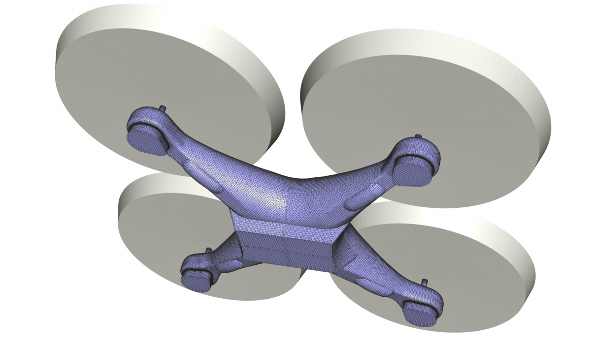 Rotating blocks (in grey) and surface mesh on the quadcopter airframe. A graphical mirroring is applied to a sector to recover a full drone geometry for visualisation purposes
 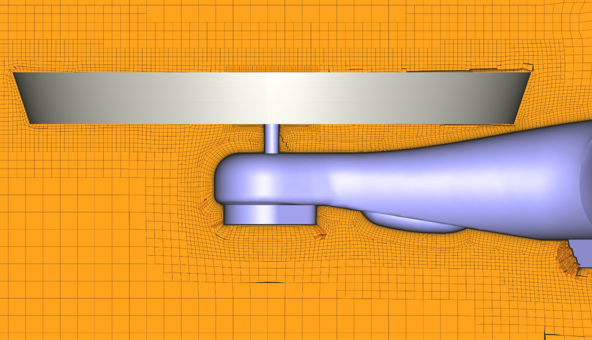 Rotating block (in grey) and volume mesh around the quadcopter airframe
 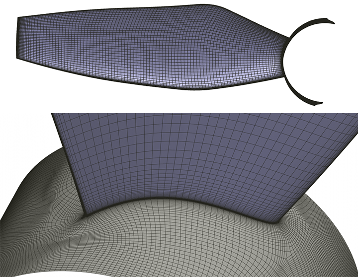 Mesh on the quadcopter blade and hub for the rotating block
 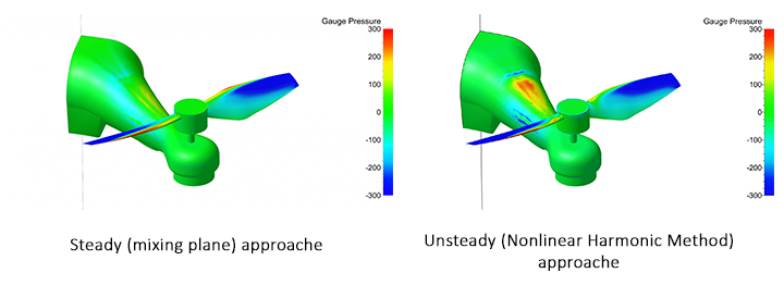 The threshold contour of gauge pressure field on propeller and airframe for a) steady (mixing plane) and b) unsteady (Nonlinear Harmonic Method) approaches?
 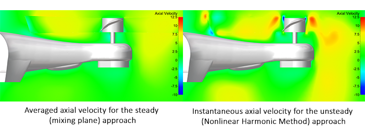 The threshold contour for the fields of a) averaged axial velocity for the steady (mixing plane) approach and b) instantaneous axial velocity for the unsteady (Nonlinear Harmonic Method) approach
  example of geometry parametrization and its variation in the framework