Renault: Aerodynamic optimization of Exhaust Gas Recirculation (EGR) for car compressors
Automotive | Turbomachinery | Optimisation | Meshing
Pollution and fuel consumption are the most important features of thermal engines that must be drastically improved in the coming years. With soaring pollution in cities around the world, legislators are demanding car manufacturers to put systems on the market that are as clean and efficient as possible, whatever the driving style or conditions, from traffic jams to highload mountain trips, in hot and cold conditions.
Furthermore to reduce CO2 levels, thus diminishing the effects on global warming, fuel consumption must be significantly limited in those same real-world usage conditions. These environmental pressures are translated into legislation: the newest EU7 emission rules and new CAFE regulation will be implemented in Europe from 2023.
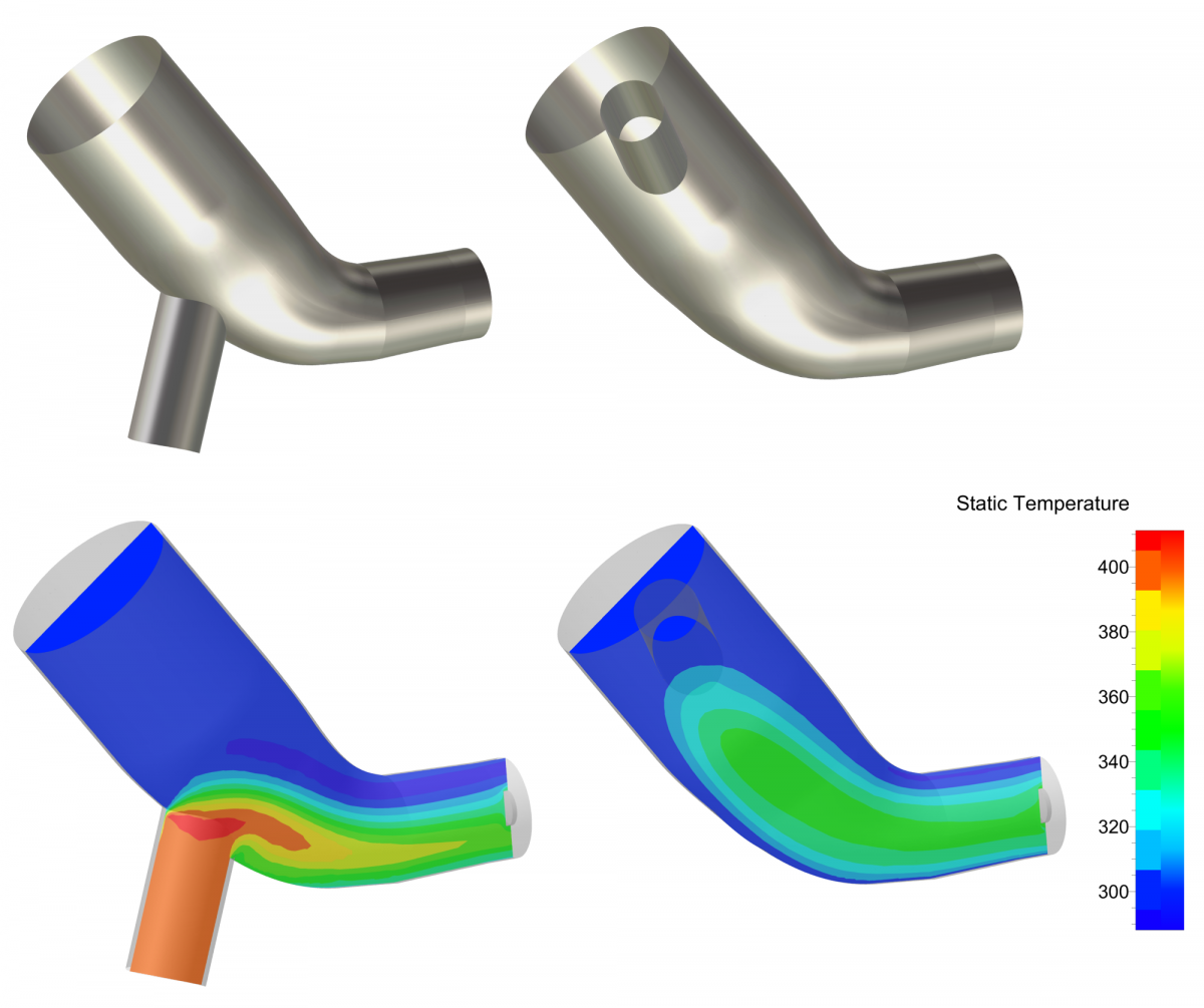
In order to achieve these goals, all consuming parts of cars are being meticulously analyzed to try and decrease losses to the maximum through design improvements, while taking into account inherent negative effects such as condensation issues for the compressor. It is within this framework that Renault turned to Numflo – the consulting group of NUMECA International, which is renowned for its top-level expertise in multiphysics design and analysis. The specific focus of the first study was to evaluate the impact of Low Temperature Exhaust Gas Recirculation (LT-EGR) on the efficiency of their turbo-compressors through CFD analysis. The power and reliability of NUMECA software tools were crucial for this project. At the end of the study, using the flow solutions obtained by Numflo, Renault performed condensation analyses with dedicated software. Condensation can indeed occur when ambient temperatures are low and, in the long term, can damage the blades and create icing problems.
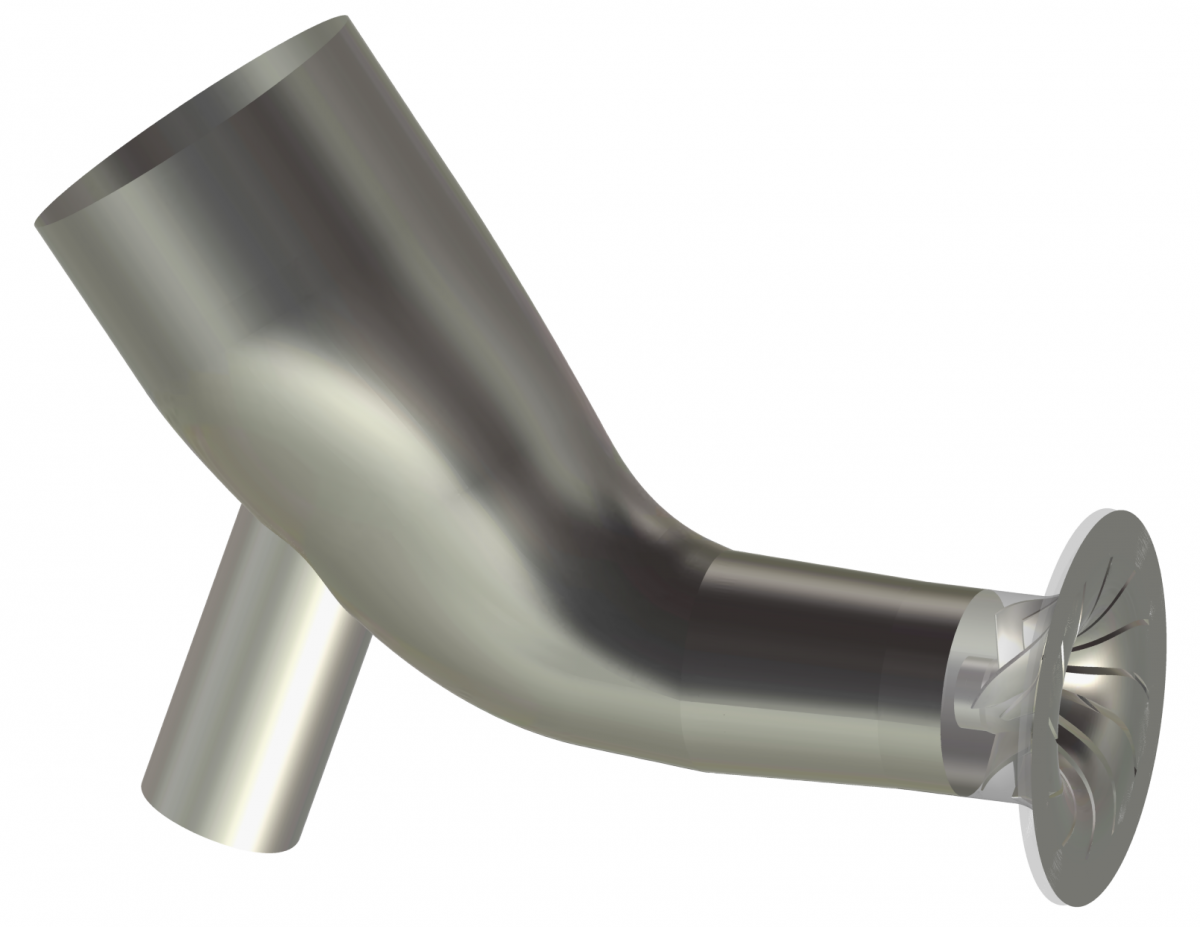
Geometry
The study focuses on the impact of 5 geometrical parameters of the LT-EGR injection on the compressor wheel efficiency:
- Radius of the EGR injection
- Axial distance between the EGR injection and the compressor
- Three angles defining the orientation of the EGR around the inlet pipe.
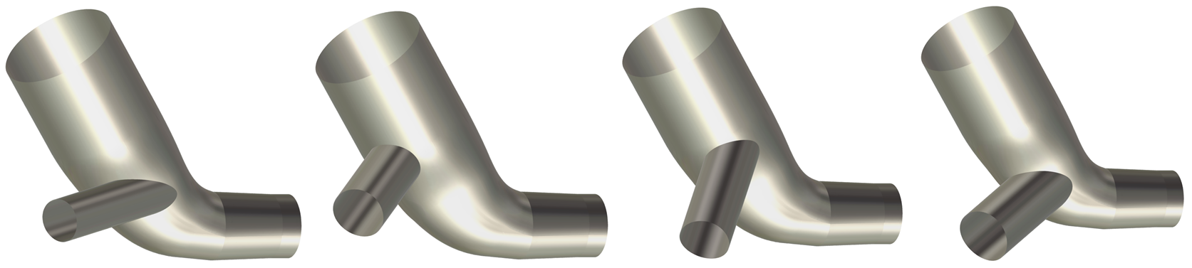
The EGR geometry is generated using the IGG™ block structured mesher, with a script. This script automatically generates a new geometry for each new set of the 5 parameters. The inlet pipe and the compressor wheel are provided by Renault and remain unchanged during the simulation process.
Meshing
On the numerical side, the meshing of the wheel consists of a high-fidelity block-structured grid, created with the automatic mesh generator AutoGrid5™. Only one periodic channel of the ,wheel is meshed. For the inlet pipe and the EGR, an automatic unstructured mesh is generated with HEXPRESS™/Hybrid software. The meshing process of the inlet pipe and EGR is automated using a dedicated script, ensuring good quality
meshes regardless of the position of the EGR. Then, both meshes are reassembled, creating the final mesh used for the CFD simulations.
Non-Linear Harmonic approach
Flow distortion introduced by the inlet pipe and EGR inside the impeller is considered by means of the innovative Non-Linear Harmonic (NLH) method in FINE™/Open. This approach solves flow perturbations in the frequency domain, allowing for high accuracy of numerical results in comparison with state-of–the-art time-marching models, at a significantly reduced computation cost. This approach allows for transmitting the 360° flow distortion generated inside the inlet pipe into the wheel, having a direct impact on its aerodynamic performances.
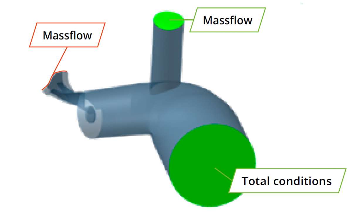
Simulations set-up
The fluid is air considered as a perfect gas. The following boundary conditions are used:
- Main inlet : Total conditions and the flow direction
- Secondary inlet : Massflow
- Main outlet : Massflow
The first solution is started using constant values per domain.
Results
The DoE (Design of Experiments) is generated using FINE™/Design3D with the Minamo module. A total of 26 elements is generated randomly using a « Latinized Centroidal Voronoi Tessellation » law. The analysis of the results of the database shows that higher wheel efficiency is obtained for an EGR located far from the wheel, and for an EGR with a small radius. Further flow analysis indicates that the best configurations demonstrate an important mixture between the main flow and the flow coming from the EGR, leading to less distortion at the inlet of the compressor wheel.
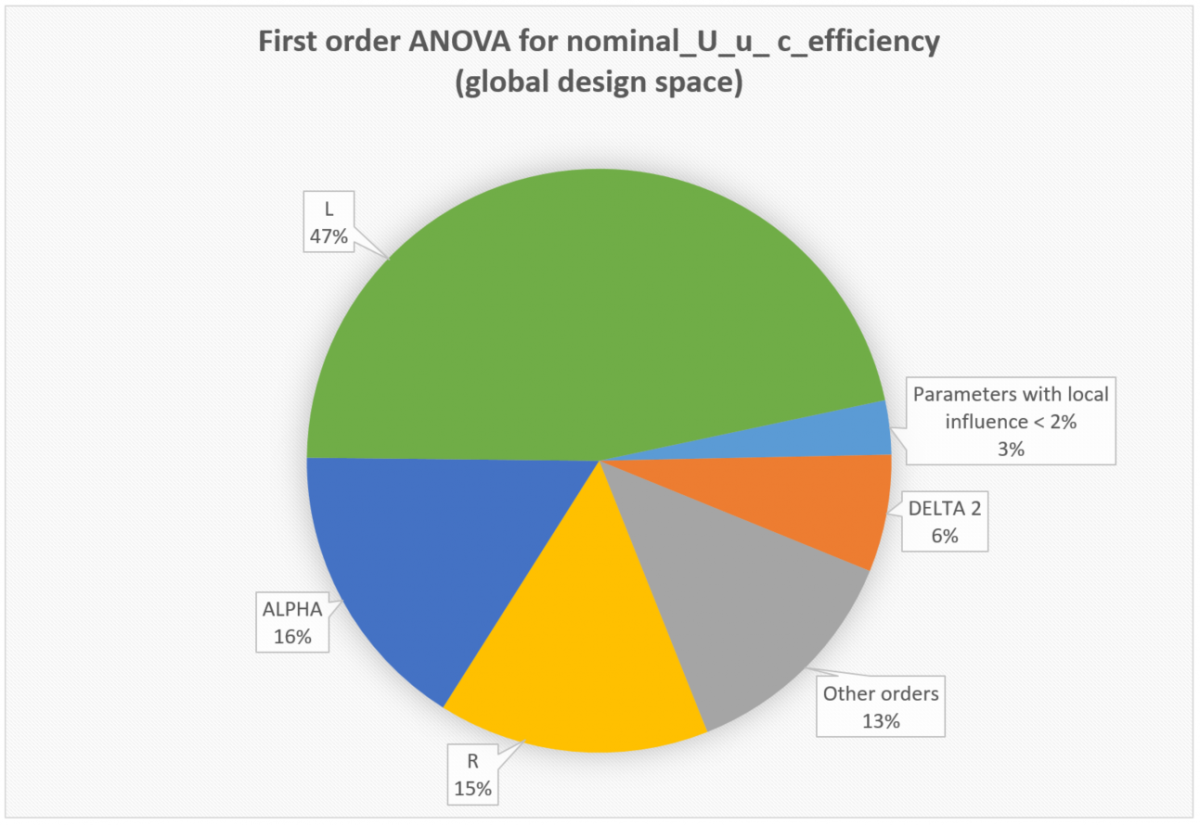
Based on the Minamo module, it is possible to run a deep analysis of the database to understand the influence and the relation between the free parameters and their impact on the performances. Below, an “ANOVA” graphic is providing the global sensibility of the free parameters for the considered objective.
“Higher wheel efficiency is obtained for an EGR located far from the wheel, and for an EGR with a small radius.”
A “Self organizing map” can also be used to project multidimensional data on a 2D plot. Based on an objective, it can easily allow the engineer to check if the available free parameters have (or not) the same impact on the objective. An example is provided below for the free parameters and a given objective. The highest value of the objective (green rectangle) corresponds to high values of “L” and low values of the “GAMMA”.
Conclusions
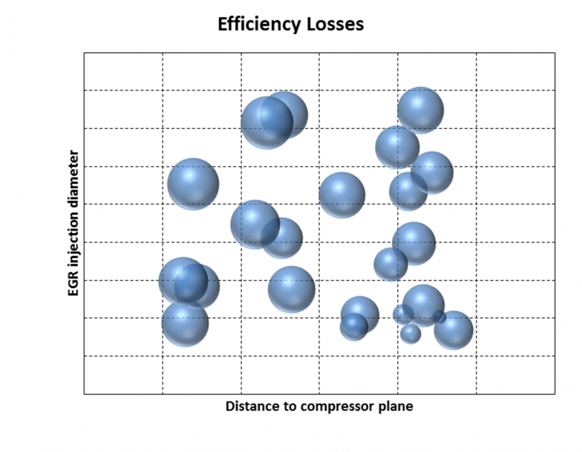
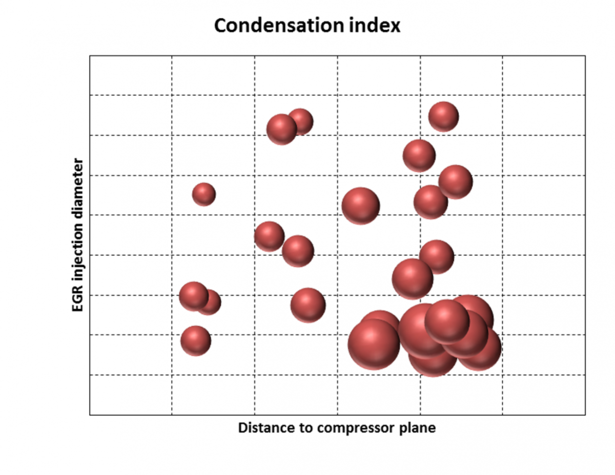
The condensation analyses performed by Renault, based on the Numflo CFD results, demonstrate that improvement of the wheel efficiency and improvement of the condensation issues lead to a selection of opposite values of the free parameters. In other words, if we want to increase the wheel efficiency, we inevitably also increase the condensation phenomenon.
The figures below show the impact of the two most important geometrical parameters of the EGR (distance to compressor plane and EGR injection diameter) on the efficiency losses and condensation index. The size of the bubbles is proportional to the losses and condensation level. From the left graph, it can be seen that losses are minimal for a high distance of the EGR to compressor plane and for a small radius of the EGR. However, this region corresponds to the worst condensation index. A compromise has to be performed between best efficiency and low condensation index as these 2 objectives are antagonistic.
The next step will be to perform an optimization taking into account the CFD (aerodynamic phenomenon) and the condensation aspects in a coupled manner.
Authors
Stephane Guilain, Tech. Expert in PWT Aerodynamic and Engine Air Filling DEA-MA – Advanced Engineering, Renault
Donavan Dieu, Senior Consulting Engineer, Numflo