Fluid dynamics investigation of the sonic boom on a supersonic aircraft concept
Aircraft | Supersonic
The return to supersonic flight is amongst the hottest topics in aviation today, as several companies (Boom Supersonic and Aerion, among others) are actively developing new supersonic commercial airliners targeted to enter in service in the coming years. In this context, a quiet flight over land is one of the major challenges to ensure the regulatory compliance of such airliners. Several research centers and companies are building demonstrators to show large sonic boom reductions with smarter designs of all the parts of the aircraft.
The nature of the sonic boom is associated with shockwaves that are longitudinal waves generated by an object that travels faster than the speed of sound. Such shockwaves caused by large supersonic aircraft are perceived by people on the ground as a sound similar to an explosion or thunder.
Exposure to aircraft noise is known to be linked to health issues, such as disturbance of sleep, developmental delays in children, obesity, and cardiovascular problems [1]. The International Council on Clean Transportation report published in 2019 warns that a network of 2,000 supersonic aircraft linking 500 city-city pairs would potentially create sonic booms as frequently as once per five minutes in some regions [2]. In view of an imminent return to commercial supersonic flight, the issue of supersonic aircraft noise is back in the spotlight of the industry and research community.
Recent research proves that it is possible to mitigate the sonic boom issue via a careful shaping of the vehicle geometry. The idea behind the low-boom supersonic aircraft concepts is the minimization of the amplitude of longitudinal sound waves also called N-waves.One of the most cutting-edge supersonic aircraft concepts, Lockheed Martin’s X-59 Quiet SuperSonic Technology (X-59 QueSST) X-plane (Figure 1), is set to take-off for its maiden flight in 2021. One of the mission goals is to provide comprehensive statistical data to regulatory authorities in order to introduce changes enabling supersonic airliners flight over land.
In preparation for the X-59 testing campaign, NASA is testing its modernized imaging system that produces high-quality air-to-air Schlieren photography. These experiments gather vital data related to the interaction of shockwaves produced by two T-38 aircraft flying in formation (Figure 2). This type of new high-quality experimental data paves a way to wider use of validated numerical simulation technologies in the development and certification of supersonic aircraft.
The use of CFD in the field of supersonic aeronautics significantly cuts the time to market and associated development costs. Sonic Boom Prediction Workshops organized by NASA aim at assessment of the sonic boom prediction methods reliability. The near-field pressure signatures prediction with CFD is perhaps its key component. Every subsequent workshop features cases with lower noise signatures, thus bringing new challenges for CFD codes. NUMECA is active in this field and was involved in the CFD investigation of a sonic boom and aerodynamic prediction of NASA Concept 25D Powered supersonic aircraft developed in the framework of recent research work [5,6].
Meshing strategy
One of the key objectives of the workshop is to assess the impact of different refinement techniques involving mesh alignment and adaptation. Despite the numerous challenges in supersonic aerodynamics, certain flow aspects can be described using fairly simple analytical expressions. One of these aspects is the Mach cone (Figure 3): shockwaves around a supersonic pointy object with a small cone angle. The cone angle of the shock waves can be determined from the cone angle of the object, and the speed of the object relative to the speed of sound, i.e. the Mach number. This flow property was employed by NUMECA to build a grid where hexahedral far-field cells are aligned with the shock wave.
In the framework of the investigation, NUMECA has built a series of 3 grids (e.g. Figure 4) for C25D aircraft in HEXPRESS™/Hybrid with equivalent settings on the surface. The only difference between grids is linked to volume mesh resolution and cell orientation in the far-field in the vicinity and below the aircraft.
| Cell count, million | Cell size in the far-field, meters | |
| Orthogonal far-field mesh | 46.6 | 0.2 |
| Orthogonal far-field refined mesh | 90 | 0.1 |
| Aligned far-field refined mesh | 105 | 0.1 |
Table 1: Summary of the grids generated for NASA C25D aircraft
When compared to grids generated by NASA and used by most of the workshop participants, NUMECA has managed to significantly improve mesh quality (Figure 5). This led to more accurate results. The CFD solver robustness is also significantly improved allowing the use of higher CFL numbers and hence faster convergence.
Simulation results
The operating point defined in the workshop [8], that is a supersonic flight at Mach 1.6 at an altitude of 15760 meters, is considered. The operation of the engine is taken into account by imposing the pressure at the inlet of the compressor, the so-called aerodynamic interface plane, and the total quantities at the engine exhaust.
In order to speed up the computation, only half of an airplane was studied by imposing relevant mirror boundary conditions on the symmetry plane. The dedicated supersonic inlet and outlet boundary conditions are used at the external domain boundaries.
In supersonic cases, flow quantities cannot be prescribed as boundary conditions at an outlet. Hence the pressure is prescribed at the inlet. This property of supersonic flow also allows creating much smaller domains compared to subsonic flow problems without any impact on the accuracy of the results. Therefore, a relatively small streamwise domain size is used while boundaries are aligned with shockwaves (Figure 7).
First, the prediction of the aerodynamic forces was investigated. It was found to be insensitive to volume mesh refinement and alignment settings. The result on the coarsest 46.6M NUMECA mesh compares well to the one from NASA Langley Research Center obtained on mixed-element 194M mesh that is considered as a reference, as shown in the following table.
| Reference data (194.4M cells, Spalart-Allmaras) | NUMECA result (46.6M cells, k-omega SST) | ||
| Lift coefficient | 0.0535 | 0.0537 | |
| Drag coefficient | 0.0329 | 0.0323 | |
Table 2: Aerodynamic forces prediction for C25D Powered aircraft
Then, the sonic boom was investigated by studying pressure disturbance distribution in the near-field of the aircraft. This is a crucial step for computational sonic boom prediction since this distribution extracted from a CFD simulation serves as an input for dedicated solvers methods (e.g. ZEPHYRUS code by NASA) allowing to study sonic boom propagation down to the ground level. The reference data used for comparison is the average pressure distribution of the workshop entries on the finest 194.4M mesh (Figure 8).
A sensitivity analysis has revealed that the turbulence modelling technique has a rather small impact on the pressure distribution prediction at the concerned locations. All of the results presented in the article are obtained with the k-omega SST model.
Sensitivity to grid refinement (Figure 9). The comparison between 46.6M and 90M orthogonal grids reveals that closer to the airplane the N-wave i.e. pressure oscillation with the highest amplitude can be captured well with both grids. Nevertheless, the finer grid shows a clear superiority in predicting smaller amplitude pressure oscillations while this grid also becomes a must to accurately predict the pressure profile further away from the aircraft.
Sensitivity to grid alignment (Figure 10). The comparison between 90M orthogonal and 105M aligned grids reveals the crucial importance of grid alignment for the cases where the highest accuracy standards are targeted. The aligned grid allows the precise capturing of the large-amplitude N-wave sonic boom as well as all of the smaller pressure oscillations.
Sensitivity to numerical scheme (Figure 11). An analysis regarding numerical schemes has shown a clear superiority of NUMECA’s cutting-edge Low-Diffusive Flux Splitting Scheme (LDFSS) that is retained for the presented simulation results. Compared to the standard central scheme of Jameson–Schmidt–Turkel, the LDFSS ensures a considerably closer match to the reference data.
NUMECA’s tools allow an efficient visualization of shockwaves pattern around a supersonic airplane using numerical Schlieren images (Figure 12). This technique can be used for detailed studying of sonic boom formation on an airplane. In this case, it shows that the strongest shockwave is formed at the aft fuselage part. The downstream pressure oscillations that were the most challenging to predict in the framework of the mesh sensitivity analysis are coming from shockwaves interacting with the engine exhaust plume.
Conclusions
Sonic boom prediction is one of the main supersonic aeronautics challenges. The present study shows that NUMECA’s cutting-edge CFD technologies can be efficiently applied in a supersonic aircraft design cycle. Challenging numerical simulations such as sonic boom prediction studies can be accurately addressed in a straightforward manner. NUMECA’s Open-DBS solver with state-of-the-art numerical schemes and tailored full hexahedral meshing approach, led to accurate forces and sonic boom predictions with a lower cell count and a lower computational effort than the reference.
The investigation also underlines the importance of best practices and know-how for meshing and simulation, some of which are demonstrated in this study.
References
1. Aircraft noise and health effects: Recent findings. Civil Aviation Authority, report CAP 1278, 2016
2. Rutherford D, Graver B, Chen C. Noise and climate impacts of an unconstrained commercial supersonic network. International Council on Clean Transportation, working paper 2019-02, 2019
3. https://www.nasa.gov/sites/default/files/atoms/files/low-boom-litho-updated-jan2020.pdf
4. https://www.nasa.gov/centers/armstrong/features/supersonic-shockwave-interaction.html
5. Wintzer M, Ordaz I. Under-Track CFD-Based Shape Optimization for a Low-Boom Demonstrator Concept. 33rd AIAA Applied Aerodynamics Conference, 2015.
6. Ordaz I, Wintzer M and Rallabhandi SK. Full-Carpet Design of a Low-Boom Demonstrator Concept. 33rd AIAA Applied Aerodynamics Conference, 2015
7. http://wordpress.mrreid.org/2012/12/15/sonic-booms-and-mach-cones/
8. Park M. Second AIAA Sonic Boom Prediction Workshop Nearfield CFD Introduction. NASA Langley Research Center, presentation.
Author
Artemii Sattarov is a CFD Application Engineer at the headquarters of NUMECA International. He holds BSc in Aerospace Engineering and MSc in Computational Mechanics. His double degree Erasmus Master’s studies were held at UPC BarcelonaTech and Swansea University. Prior to joining the company in 2017, Artemii was an intern at ANTONOV company, CFD research assistant at Barcelona Supercomputing Center, and student demonstrator assistant at Swansea University.
Products
![Figure 1: Lockheed Martin X 59 QueSST Aricraft Concept [3]](https://www.numeca.de/wp-content/uploads/2020/09/Figure1_Lockheed-Martin-X-59-QueSST-aricraft-concept-3.png) Figure 1: Lockheed Martin X 59 QueSST Aricraft Concept [3]
Figure 1: Lockheed Martin X 59 QueSST Aricraft Concept [3] ![Figure 2: Schlieren Photography Revealing The Interaction Of Shockwaves Produced By Two T 38 Flying In Formation At A Supersonic Speed [4]](https://www.numeca.de/wp-content/uploads/2020/09/Figure-2-Schlieren-photography-revealing-the-interaction-of-shockwaves-produced-by-two-T-38-flying-in-formation-at-a-supersonic-speed-4.jpg) Figure 2: Schlieren Photography Revealing The Interaction Of Shockwaves Produced By Two T 38 Flying In Formation At A Supersonic Speed [4]
Figure 2: Schlieren Photography Revealing The Interaction Of Shockwaves Produced By Two T 38 Flying In Formation At A Supersonic Speed [4] ![Figure 3: Schlieren Image Of Mach Cone Formed By A Bullet [7]](https://www.numeca.de/wp-content/uploads/2020/09/Figure-3-Schlieren-image-of-Mach-cone-formed-by-a-bullet-7.jpg) Figure 3: Schlieren Image Of Mach Cone Formed By A Bullet [7]
Figure 3: Schlieren Image Of Mach Cone Formed By A Bullet [7] 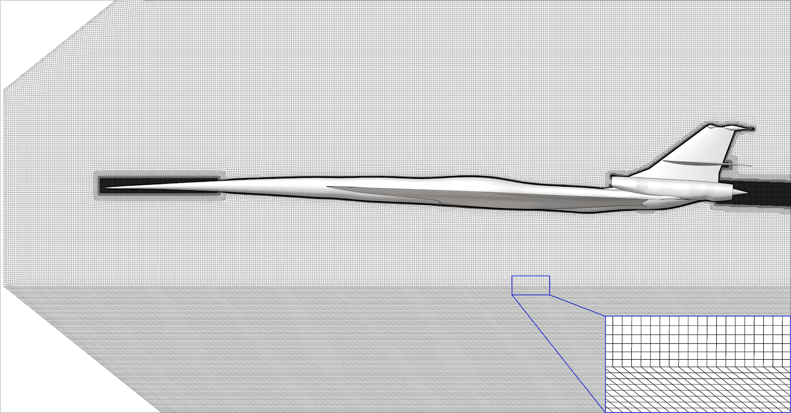 Figure 4: Mesh On The Longitudinal Plane For The Case Of Aligned Grid
  Figure 5: Histograms Of Equiangular Skewness Of The Meshes
 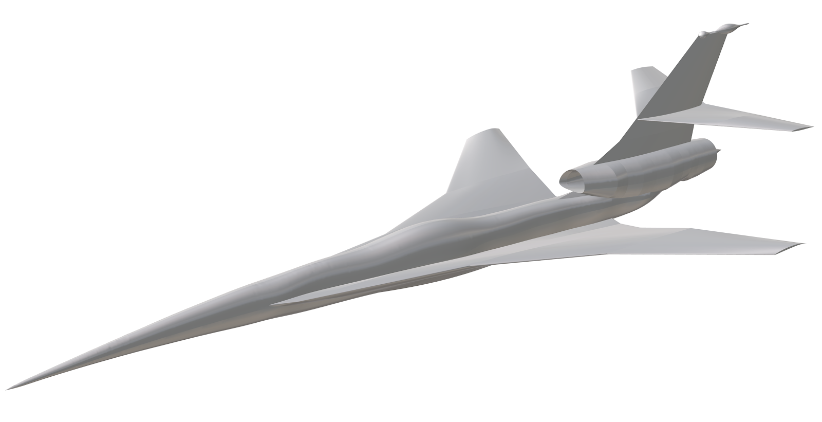 Figure 6: C25D Aircraft Geometry
 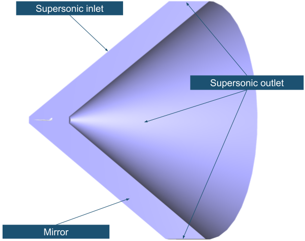 Figure 7: Computational Domain And Boundary Conditions On The External Domain Boundary
 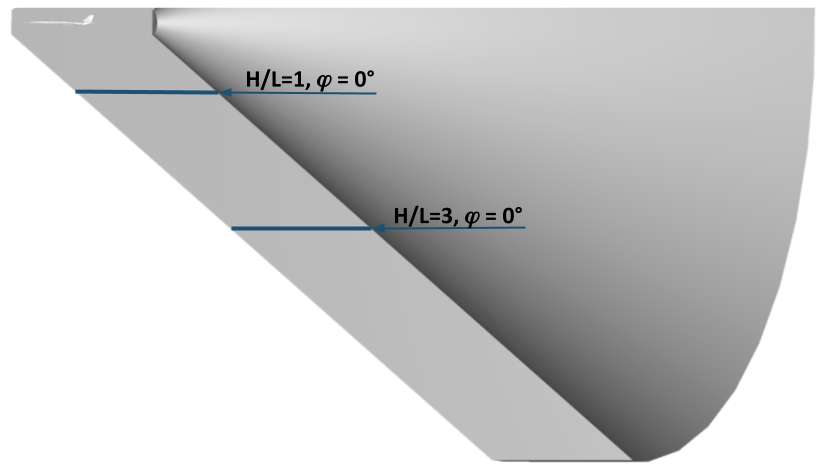 Figure 8: Pressure Distribution Comparison Locations. H Is The Distance In Yaw Axis Direction; L Is The C25D Aircraft Length.
  Figure 9: a) Comparison of normalized pressure disturbance profile between 46.6M and 90M orthogonal meshes to the workshop entries average on the finest 194.4M mesh at the location corresponding to a) 1 length below the airplane b) 3 length below the airplane
 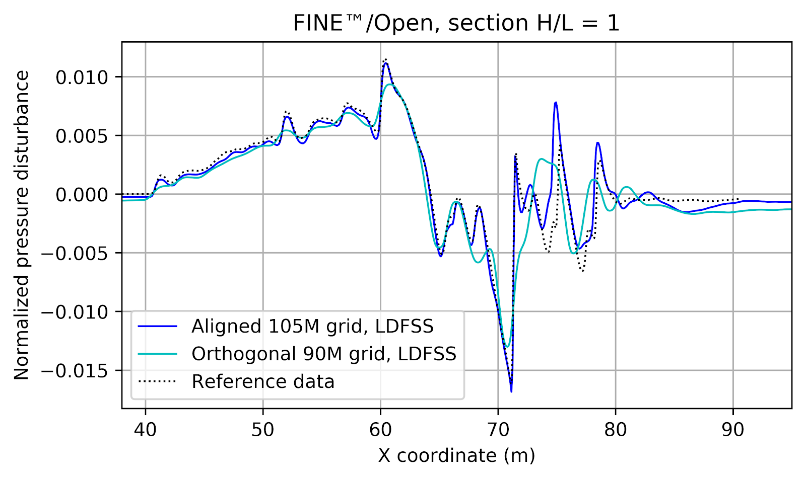 Figure 10: Comparison of normalized pressure disturbance profile between 90M orthogonal and 105M aligned meshes at the location corresponding to 1 length below the airplane
 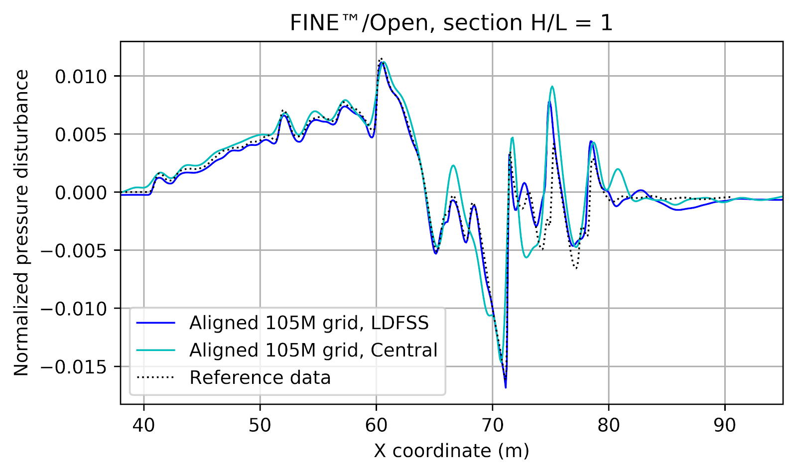 Figure 11: Comparison of normalized pressure disturbance profile between LDFSS and central scheme with scalar dissipation using the 105M aligned mesh. The location corresponds to 1 length below the airplane
 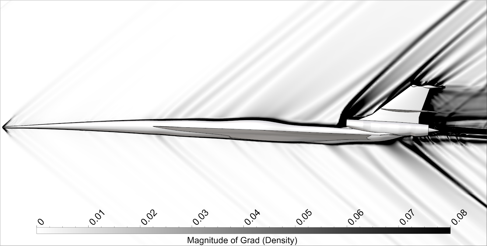 Figure 12: Numerical Schlieren Images On The Longitudinal Plane Depicting The Shockwaves Pattern Around The Aircraft