Reducing fuel usage with ship trim optimisation in FINE™/Marine
Trim | Marine | Ship Design
Ship trim optimisation has recently gained enormous momentum as it can significantly reduce fuel consumption and curb emissions. The drag on a ship changes with the trim angle for the same speed and average draft. As such, imposing an optimised trim angle during the loading process in the harbour ensures a minimal average resistance during the vessel’s journey.
The financial benefits of trim optimisation
Because of the potential for reduced fuel costs, it becomes financially interesting to create a database of optimum trim angles based on a complete trim optimization study for various cruise conditions. Besides, trim optimisation can be performed regardless of vessel type and age, although the size of the benefit depends on the vessel type. For some vessels, e.g. cruise ships, the trim angle cannot be adjusted with the same flexibility, since passenger comfort and facilities impose relatively strict constraints. The benefit is the largest for ships often sailing in part-load conditions such as ro-ro carriers and smaller containerships, with fuel savings up to 5%. For a container feeder of about 2000 TEU, sailing at 22kn, this would correspond to a savings of about 35 barrels of oil per day [source]!
The importance of dynamic trim
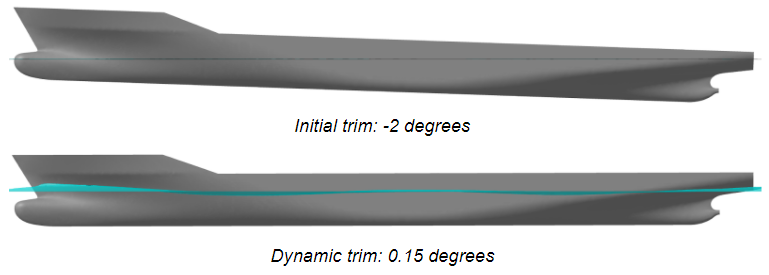
In the past, ships were optimised for a single speed and draft even if the ship experienced a wide range of different conditions, requiring changes to the ship speed and the draft. Now, computational fluid dynamics (CFD) is a game-changing tool to generate a matrix of optimal trim and draft conditions quickly and with great accuracy. The fact that the trim of a ship is voluntarily changed from the static position in a harbour will affect the dynamic trim when sailing, so it also has to be taken into account in the calculations.
Hundreds of simulations, one for each combination of initial trim, draft and speed, need to be run to create the optimal trim database, ruling out model testing. Additionally, the computations are performed directly at full scale. This set-up was shown to be required to accurately predict the effects of turbulence which clearly affects the optimum trim angles. Local recirculation and flow detachment can lead to different force predictions between model- and full scale as the Reynolds number, which governs these phenomena, cannot be preserved in the geometrical scaling. Compared to potential code, which doesn’t include the effects of turbulence, the resistance-increasing effects of wall-roughness (fouling) can be also included in the CFD analysis. As such, CFD can provide a much more realistic result of ship resistance during the entire lifetime.
Given the accuracy and consistency of the results, CFD also brings detailed information to complex hydrodynamic problems in a 3D space. The workflow can also be automated to a very high level, as all required actions from the software can be scripted. A naval architect or marine engineer simply needs to enter the real ship conditions, and the software sets up and runs all simulations rapidly and autonomously on a single workstation or HPC cluster.
Our approach
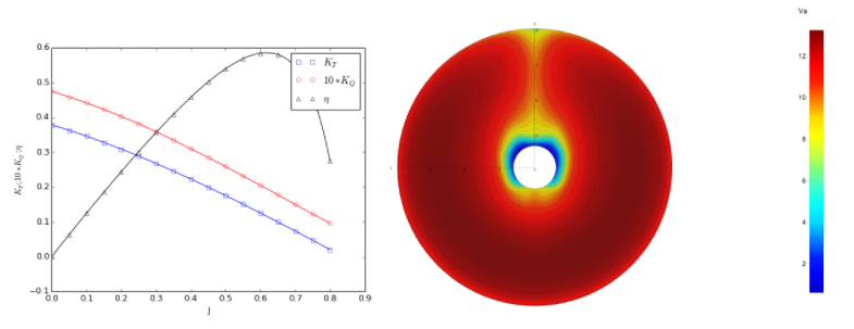
In practice, FINE™/Marine’s C-Wizard matrix mode creates n x m x p computations: one per {draft (n), trim (m)}-couple for the provided list of speeds (p). The displacement is kept the same for all draft-trim combinations. The Z-coordinate of the free surface also remains the same for all computations, as the ship is translated/ rotated to ensure iso-displacement conditions. The user also has the option to use open-water data for real propeller performances through an actuator disk (Figure 2). This further increases the accuracy and realism of the results keeping a low CPU cost.
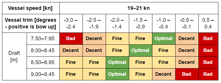
The drag forces, moments and dynamic trim and sinkage computed by the flow solver are written out for each combination of (draft, trim, velocity) in the post-processing step, which also yields the displacement at each draft. As an example, Figure 3 shown an optimised trim table for a particular vessel that can be prepared based on the CFD results obtained from FINE™/Marine.
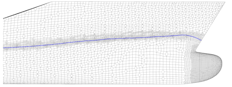
It is interesting to note that the whole project for all the hundreds of computations will be performed with one single mesh! This capability significantly reduces the total computation time due to only meshing the geometry and domain once, and it also ensures that the accuracy is just as high. The numerical uncertainty inherent to the creation of different meshes is removed simultaneously, achieved via FINE™/Marine’s unique adaptive grid refinement (Figure 4), which takes care of all the unnecessary refinement for the free-surface, during the simulation, in an anisotropic, automatic and dynamic way.
Conclusion
Trim optimisation is a relatively easy method for ship owners to reduce operational expenses. While in the past it may not have been possible to obtain accurate resistance predictions for a large matrix of initial drafts, trim angles and velocities, CFD is now the tool of choice to obtain a database of optimal trim angles quickly and with high accuracy. The unique features of FINE™/Marine, such as a single-mesh approach with adaptive grid refinement and the usage of real open-water data for propulsion, position the software as the ultimate CFD toolbox for matrix-based resistance applications.