A somewhat unusual Turbine Architecture (OTH-AW)
Turbomachinery | Grid Generation
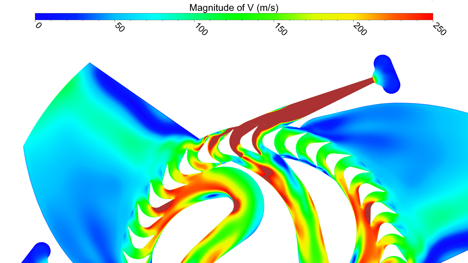
You think you have seen them all? Take a look at the animation in Figure 1 and prepare to be surprised. What you are seeing is a first impression of one of the latest projects of Prof. Dr. Andreas P. Weiß and his team at the OTH[1] Amberg-Weiden – the so called “Elektra-Turbine”. It is a redesign of a radial re-entry cantilever turbine, originally invented at the beginning of the 20th century. At the time, these turbines (20 – 300 kW) were applied on ships to directly drive pumps and fans at very low rotational speeds (equal to 3000 rpm). The general idea of the current research project is to investigate rather uncommon turbine concepts which bear the potential to be used in small, decentralized power plants. As a first step, a 5 kW air-driven redesign has been built and investigated both experimentally and numerically in cooperation with NUMECA Ingenieurbüro.
Since this turbine is not particularly a standard design, the reader is familiarized with the flow path at first: Pressurized air (p0 approximately equals 10 bar) enters the turbine stage and is subsequently accelerated in a supersonic nozzle where it reaches a Mach number of nearly 2.7. The flow then passes the rotor twice, converting this kinetic energy into mechanical work at a ratio of 3 to 1 like in a Curtis stage The preliminary design of this geometry was developed by OTH-AW with an 1D turbine design tool, also supported by means of 3D CFD-simulations. Both steady and unsteady RANS-methods were applied using the EURANUS flow solver from NUMECA.
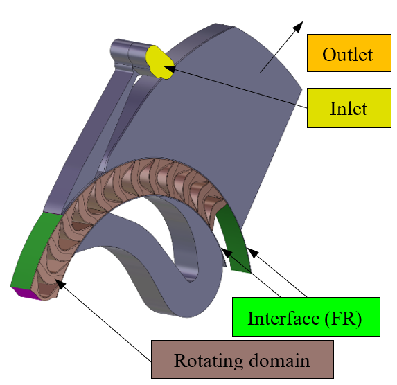
The simulation model incorporates one periodic pitch which extends over 120° for this case. It has been meshed with a fully structured multi-block grid by means of NUMECA’s meshing tools IGG™ and AutoGrid™. For the steady simulation, flow quantities are exchanged via a full non-matching frozen rotor interface between stationary and rotating domains. This approach however does not lead to a satisfactory agreement when compared with measurements of the global turbine efficiency. Instead, the average of an unsteady simulation has to be computed, in order to achieve a better match. However, the results from the steady CFD solution provide the means to obtain a first impression of the flow dynamics and to reveal some potential for further improvements of the geometry.
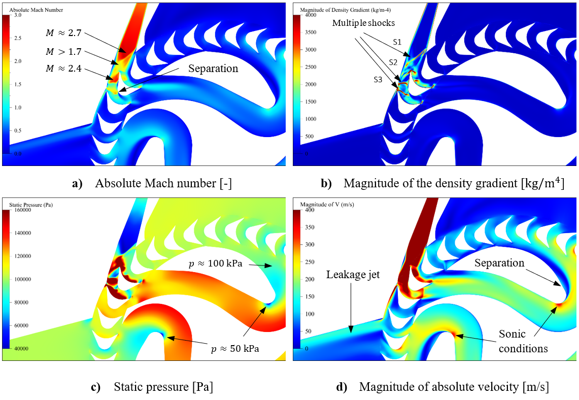
Figure 3 displays four representative flow quantities on a constant span position at 50% of the nozzle height. They stem from a steady state computation at design conditions. To begin with, the reader is referred to Figure 3 a). The flow has entered the nozzle and expands through the divergent part where it reaches a maximum Mach number of approximately 2.7. The divergent part of the nozzle terminates with a sharp edge on one side and with a minor turning on the other side (the flow is turned into it-self). Thus, the expansion stops momentarily with an oblique shock wave, labeled with shock S1 in Figure 3 b). Downstream, the flow decelerates but remains supersonic. As it approaches the leading edge of the turbine wheel, the flow is divided into two parts, each experiencing different area progressions. The “left part”, relative to the view in Figure 3 a), accelerates again to a Mach number of 2.4, since the blade is forming another diverging nozzle together with the turbine casing. Ultimately, another shock wave is formed (shock S2) leading to a strong positive pressure gradient in the streamwise direction. This might cause the considerable amount of the flow which is not entering the blade passage but passes directly over the leading edge towards the outflow instead. The leakage jet becomes clearly visible by plotting the magnitude of the absolute velocity, as can be seen in Figure 3 d). This mass flow leakage is estimated to be approximately 9% of the inlet mass flow by the steady state solution. The remaining flow overcomes the turning in the turbine with another oblique shock annotated with S3. Except for a small region with flow separation on the suction side (induced by the show waves S2 & S3), the flow remains supersonic until the blade passage diverges and guides the flow towards the deflection channel.
In this channel, the flow suffers from viscous dissipation causing a pressure loss of approximately 20 kPa. The main reason for this is twofold. First, as a result from the complex flow phenomena upstream, the flow exits the turbine with very high velocity gradients in both the circumferential and the spanwise direction. This non-uniform flow is propagated downstream which leads to an inhomogeneous flow field in the entire channel. The second reason is the significant turning of the channel in conjunction with a high ratio of the channel width to the curvature radius. The strong curvature and the associated pressure gradient normal to the inner curve leads to a very low pressure and the flow reaches sonic conditions. As a result the flow close to the inner radius has to overcome a pressure increase from approximately 50 kPa to about 100 kPa (see Figure 3 c) ) before the flow enters the turbine wheel a second time. This leads to a relatively large area with flow separation, which can be clearly seen in Figure 3 d).
Complementary to the frozen-rotor approach, a URANS computation has been conducted to analyze the influence from highly unsteady interactions throughout in the turbine, particularly between the nozzle exit and the turbine wheel. A direct comparison reveals that the mass flow leakage is about 6 percentage points higher in the unsteady simulation. Hence, 9-15% of the incoming mass flow do not contribute to the energy conversion and are practically lost. Also, the total specific enthalpy drop appears to be overestimated by the steady simulation by nearly 11%. The influence of both effects can be directly noted in the isentropic efficiency, which is predicted to be 39.8% for the unsteady case and 47.1% for the steady simulation. The measurements show an efficiency of approximately 33% – an offset of 7 percentage points compared to the unsteady average.
Based on the results of these preliminary investigations, Prof. Weiß and his team at the OTH will continue their efforts in cooperation with NUMECA Ingenieurbüro. The objective will be to reach an isentropic efficiency of a least 50%. To be continued!
[1] Ostbayerische Technische Hochschule Amberg-Weiden, Centre of Excellence for Cogeneration Technologies
Acknoledgements
The work presented was conducted within the frame of the BTHA-project (JC 2018-56) “Low cost turbo expanders for decentralized energy applications – possibilities of 3D print manufacturing from modern plastic materials” in close collaboration with colleagues at the University Centre of Energy Efficient Buildings (UCEEB) at Technical University in Prague. The authors want to thank the “Bayerisch-Tschechische Hochschul-Agentur (BTHA)” for their financial support.