Accurate Impeller-volute Interaction in Turbochargers
Turbomachinery | Automotive | HVAC | Aerospace
Turbochargers are currently ubiquitous in automobiles. It is nearly impossible to find a new Diesel vehicle without turbocharging and direct injection. Gasoline cars have been also following suit for the past few years. Regulations are pushing for lower emissions and the way to achieve this has been downsizing and using turbocharging to offset the lower power density of a smaller motor.
The turbocharger, however, adds a new degree of complexity to the system. Besides its own standalone performance, a turbocharger has to perform well with the engine. A component that is crucial in the high performance of the turbocharger inside the engine system is the volute. The volute is the component that connects the turbocharger with the inlet manifold. Often, the volute is redesigned for different engines and normally there is design freedom that can lead to minimizing the pressure losses that it introduces.
It is very important to capture appropriately the interaction between the turbomachinery components (impeller and diffuser) and the volute so as to be able to predict and minimize the pressure losses. Computational Fluid Dynamics (CFD) is frequently used for simulating this behaviour.
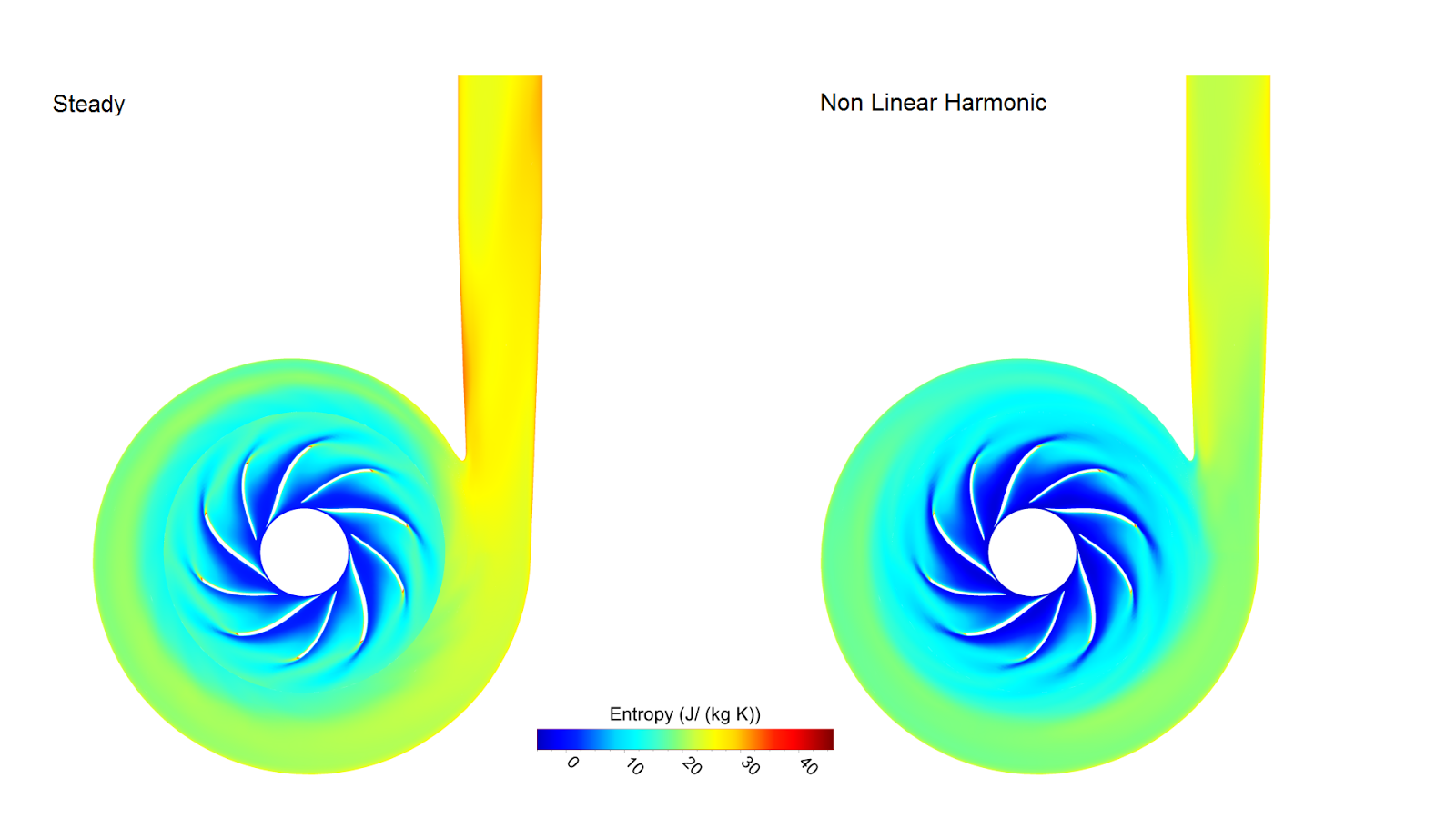
While it is possible to obtain an accurate prediction of the pressure loss by using a steady simulation, impeller-volute interaction can cause instabilities that can impact the performance of the turbocharger. For this, an unsteady analysis is used which is quite more costly and rarely happens in the design phase but rather in the validation phase of the design cycle.
To avoid running a costly analysis and for the designer to be able to incorporate this analysis in the design phase, frequency domain simulations like the Non Linear Harmonic (NLH) Method currently implemented in the NUMECA tools are employed. NLH solves the fluid equations in the frequency domain, only needs to simulate one blade passage instead of the full wheel and the equations are solved in a steady manner thus enabling the use of convergence acceleration techniques. It allows for an unsteady solution – including the transport of information through the impeller-volute interface – at a cost similar to a steady one.
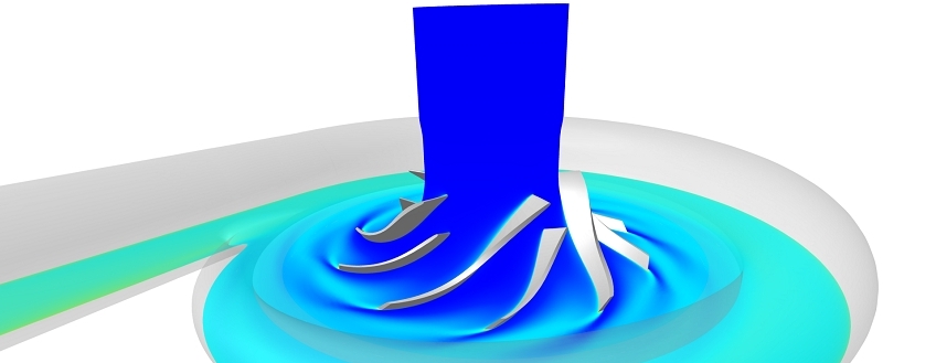
The animation shows how the pressure waves propagate from the impeller towards the volute as well as their reflection back to the impeller coming from the tongue of the volute (the area where the outlet duct meets the scroll), providing important information about how the impeller-volute interaction and interaction with the tongue.
Capturing this interaction is quite important. The reflected waves can have negative impact on the performance of the system as they can cause instabilities to the impeller such as rotating stall, increased losses and increased forcing on the blades. The phenomenon cannot be captured by a steady (mixing plane) approach due to the averaging of the flow quantities in the impeller-volute interface or by a frozen-rotor approach. Hence a costly, unsteady simulation or a more cost-efficient harmonic (NLH) simulation is the way to capture this behaviour.
This analysis can be used in any configuration, centrifugal or not, and can provide insight about the interaction between turbomachinery components and devices upstream or downstream early in the design phase while keeping the simulation cost low.