Design Optimisation of a Multi-stage Compressor
Turbomachinery | HVAC | Automotive | Aerospace
Research-and-production Company “ENTECHMACH”, located in St. Petersburg, Russia, has been operating in the power engineering area for more than 25 years. Its main activities are design and production of centrifugal and axial compressors, steam turbines, multipliers, heat exchangers with air and water cooling systems.
Since 2 years now the company has been using the FINE™/Turbo package for the flow simulation and optimisation of stationary industrial centrifugal compressors and for research engineering. One of those developments concerns the modernisation project of a three-stage air centrifugal compressor in catalytic cracking technology.
Problem Analysis
The existing compressor suffered a number of drawbacks: low reliability of the axi-radial impellers as their covering discs were causing large stress concentration zones, failing stators due to unsuitable material choices and a number of performance issues. The performance and discharge pressure were insufficient, the surge margin was too low and the power consumption too high.
As a first step we used NUMECA’s FINE™/Turbo solver to accurately calculate a complete compressor performance map of the compressor. The result allowed us to clearly identify the main causes of these efficiency losses and low surge margin. Conclusion: The modernised compressor would need a complete replacement of the rotor and stator elements in the compressor case, bearings and lubrication oil system.
Optimisation
It was decided to design the new compressor with semi-opened axi-radial impellers, as they create two times less stresses compared to the closed axi-radial version with covering discs.
To make sure the newly developed impellers meet the highest possible levels of efficiency, pressure ratio and surge margin, all flow path elements were optimised with NUMECA’s FINE™/Design3D solver including the impellers, the vane diffusers and the return channels for several operating conditions.
With the use of the NLH-method, the influence of the inlet chamber and 360° inlet guide vanes on first impeller parameters was investigated, as well as the influence of the outlet chamber on the last diffuser blade row. Combined vane diffusers, which merge a long vaneless part and a low blade density part, were implemented in all stages. The numerical investigations confirmed the advantages of this solution: a wide operating range and reduction of the losses in the stator elements (as with vaneless diffusers), but at the same time providing optimal flow conditions at the inlet of the return channels, which leads to an efficiency increase (as with vane diffusers).
The main challenge to solve for the return channel optimisation was the axial flow direction at the inlet of the next impeller. Traditional return channels with 2D profiles that we analysed, could not provide the axial flow direction on all channel spans. There were highly non-uniform flows on the hub and shroud as shown in Figure 3 on the left side.
To solve this problem, we developed a non-classic return channel consisting of two parts: a 2D main profile part and a 3D outlet part. The main part was calculated in a way that would achieve the largest possible flow irregularity decrease and the 3D outlet part was designed to have an effective flow alignment on all spans. This solution suppressed the secondary flows in the return channels considerably. In Figure 3 on the right side, where 90° equals axial flow, the irregularities after the modernisation can be seen. The redesigning of the return channels eventually resulted in an increase of the operating range of the second and third impellers of more than 15% thanks to the improved impeller inflow conditions.
The new compressor performance map was calculated again for different operating conditions i.e. different angles of incidence of the Inlet Guide Vane (IGV) and inlet temperature. The results are shown in the Figure 4.
Meshing
The full mesh model of the compressor was generated with IGG™ and AutoGrid5™. It included about 40 million elements and consisted of all blade rows, gaps between impellers and stator, outlet chamber and all labyrinth seal regions. The Spalart-Allmaras turbulence model for simulations was applied to verify the correspondence of mesh criterion y+ with a recommended range. Thanks to the high quality of the mesh we could apply the CPU Booster™ for our calculations, which saved us a lot of time and computing resources.
Results
Industrial tests of the modernised compressor showed an increase of polytropic efficiency on normal mode of ~6.5% abs. and a corresponding decrease in power consumption of the same percentage. The new compressor reaches a higher pressure ratio of 4.5, compared to 4.1 before the modernisation. Furthermore the surge margin related to the normal mode significantly increased from ~6% before to 50% after. Power consumption on minimal performance is 1.5 times lower (~2.5MW).
The new, modernised compressor is in operation at client site and performing well and equally as important is proving reliable.
Authors
Vladimir Neverov, Ivan Cheglakov, Specialists on compressor machines
Aleksandr Liubimov, Head of Advanced Development and Design Department
ENTECHMACH, Russia
Products
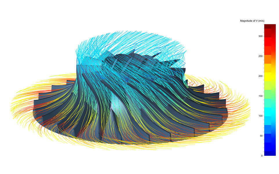 Figure 1: Second stage impeller with streamlines
 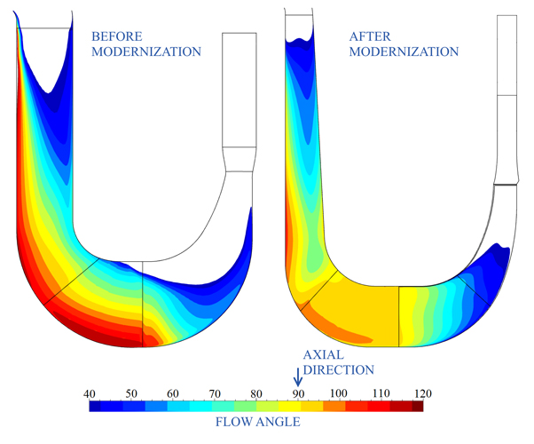 Figure 3: Flow angle
 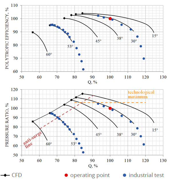 Figure 4: Compressor performance map with different angles of incidences of IGV
 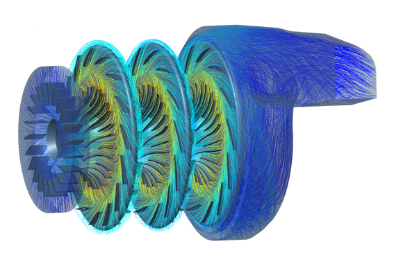 Figure 5: Full computational model of the modernised compressor
 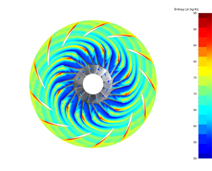 Figure 6.1: Part of the NLH reconstruction. Entropy passing through second impeller and diffuser
 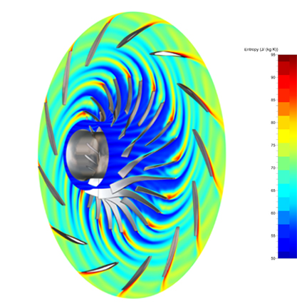 Figure 6.2: Part of the NLH reconstruction. Entropy passing through second impeller and diffuser