Multi-Disciplinary Optimisation of a FORD Turbocharger Compressor Design
Automotive | Turbomachinery | Grid Generation
There are several reasons why optimisation methods can at this time not be considered in routine design work:
- Lack of computational resources: Everybody is enjoying that those resources have increased quite a lot recently, but nevertheless design optimisation work is still seen as too costly.
- The need for multi-operating-points: For quite some time optimisation and inverse design techniques would be focused on one single operating point, with no guarantee or control of the off-design performance, choke flow, performance at lower speeds,… Investing in a significant effort without guaranteed ROI is clearly limiting the interest of designers working under pressure and with time constraints.
- The multi-disciplinary need: Especially for designs working under strong mechanical pressure, such as turbochargers, an optimisation limited to aerodynamic performance and not offering control or verification of the mechanical integrity is also not so interesting.
NUMECA’s FINE™/Design3D design optimisation software offers solutions to all 3 items mentioned above:
- We considerably optimised our solver speeds: The FINE™/Turbo solver converges in typically 30 minutes to 2 hours per million nodes and per core. With a dozen of cores, the aero-analysis of a new design at 3-4 operating conditions can be done in 2 hours! An impressive result compared to standard commercial solvers that need an entire day for this.
- Optimisation is flexible and can easily address multi-operating point problems. In the example shown below, performance is investigated and controlled from stall to choke, at different speeds.
- The flexibility of the optimisation allows for the analysis phase to include a CFD solver, but also a mechanical tool (or other solvers). NUMECA developed a partnership with the company Open Engineering, and we have coupled FINE™/Design3D with the FEA mechanical solver Oophelie.
The optimisation example case described below has been presented at the 2015 IGTI Turbo Expo conference (GT 2015-43631). NUMECA-USA collaborated with the FORD turbocharger research group on this project. We started from an initial compressor blade design that already presented quite high performance, with the objective of mainly decreasing the mechanical stress levels by 20%. No clear objectives were set on the aero-performance, apart from trying to maintain it if possible.
Mechanical Optimisation
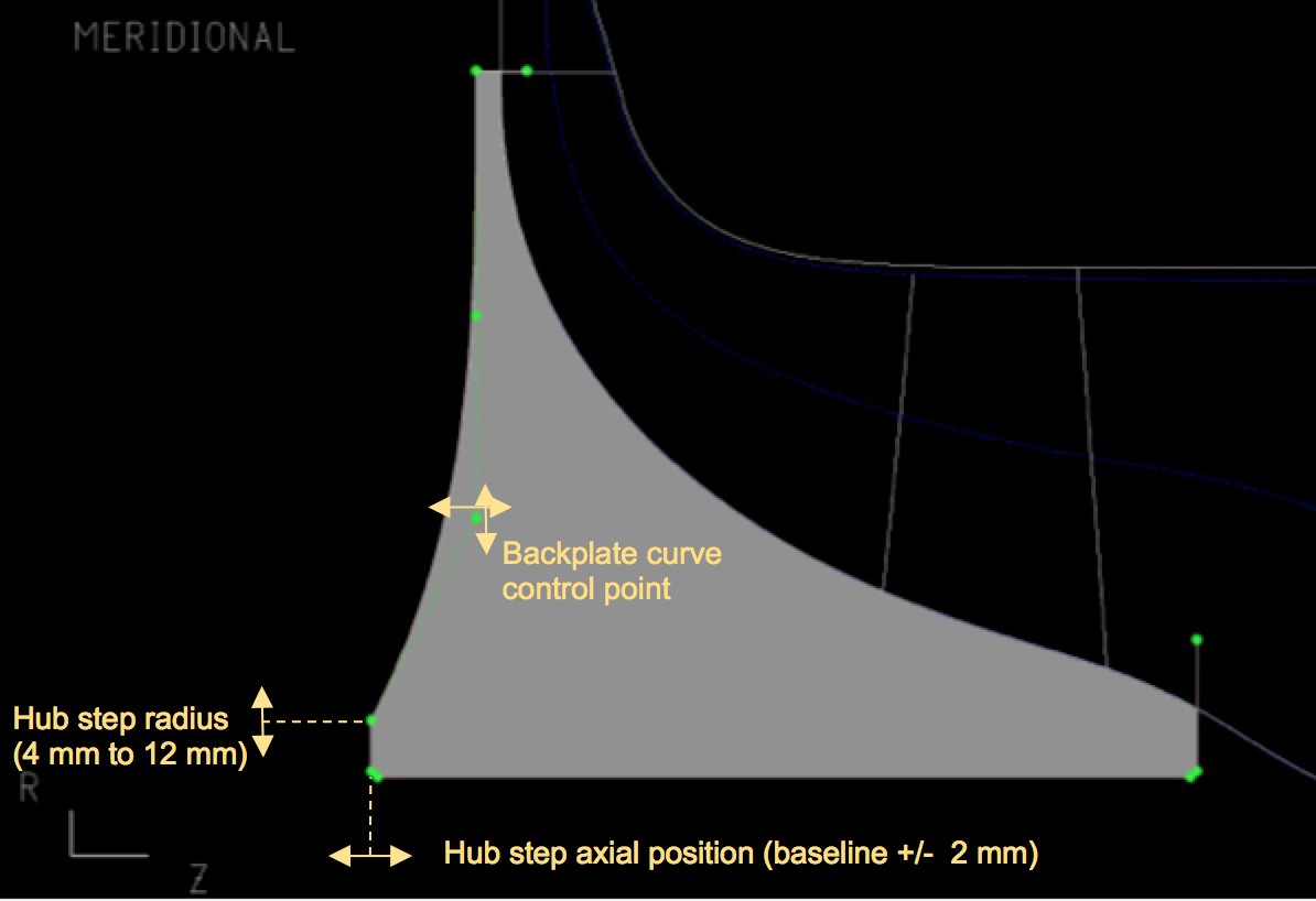
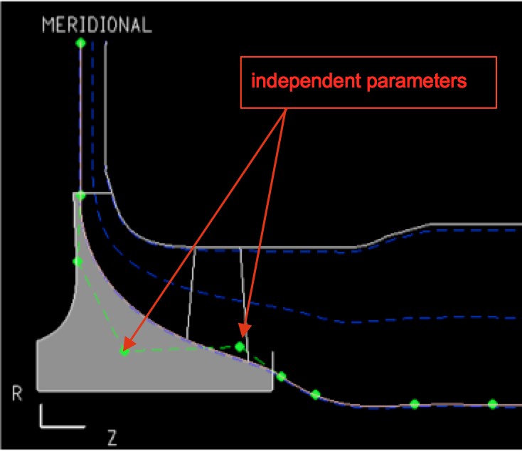
The process started with an optimisation of the back plate and bore zones, which only necessitated running the mechanical analysis tool Oophelie. The blade modeler AutoBlade™ has been upgraded to allow for the parameterisation of the back plate, as shown below. Once the design parameters are selected and variation bounds applied, our optimisation process works in 2 steps:
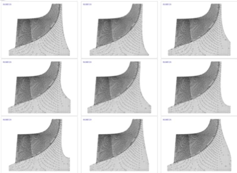
- random geometries are generated and analyzed by the FEA tool (DOE process).
- the information resulting from this first process is used by the optimiser to find the optimum.
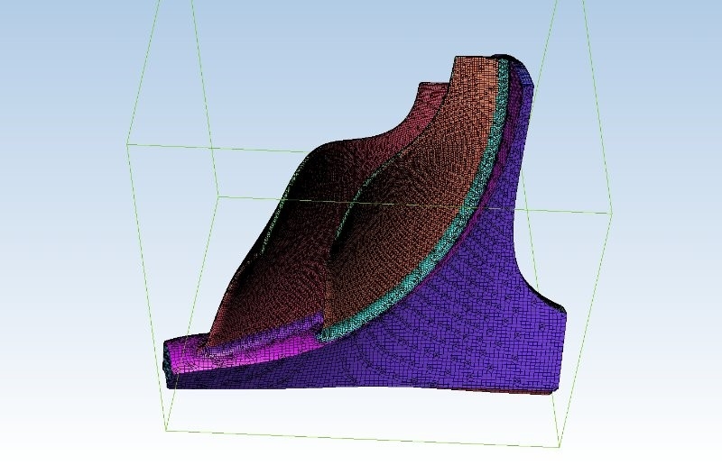
The whole analysis process is executed in batch mode. Once the parameters are selected, a CAD definition of the geometry is generated, which is provided to the mesh generator (see resulting mesh below; note that fillets are automatically applied to the blades, even if not included in the geometry). The resulting mesh is then resolved by the FEA tool.
Aero-Mechanical Optimisation
The mechanical optimisation process was done in one night. It was followed by a complete optimisation of the blade shape and meridional channel, involving both the CFD analysis tool FINE™/Turbo and the FEA solver Oophelie.
Several speed lines of the initial design have been analyzed. The computational domain includes not only the wheel, but also the volute and the casing treatment. We then decided to focus on the choke and stall conditions at design speed and on the near-stall conditions at a lower speed. This decision was made based on the assumption that the design performance would be indirectly controlled if the choke flow and near-stall performance are maintained or improved.
The blade camber lines have been parameterised, as well as the hub path, which was controlled by Bezier points. Also we included the camber line profiles of the splitter blades and their stream-wise and tangential positions. This led us to a total number of 19 parameters.
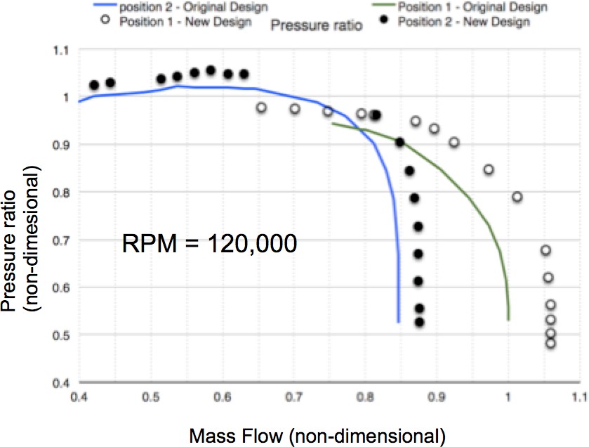
450 geometries have been randomly generated. We decided to first calculate them with the mechanical tool. This allowed us to eliminate 300 of them, as they were providing higher maximum stresses. We associated poor aero-performance to those (without actually running the CFD) and then applied the CFD solver only to the 150 better ones, saving a lot of computational time. After optimisation, a new blade design was selected, presenting slightly better pressure ratio performance, and with 20% lower mechanical stresses. The pressure ratio curves are shown beside.