Design and Analysis of a Centrifugal Compressor for Refrigeration Cycles
Turbomachinery
Preliminary Design | Thermodynamic Tables | Refrigerant Compressor | COMPAL
1. Outline
One of our most recent projects was initiated by a request from a new customer, Teqtoniq GmbH located in Horw, Switzerland[1]. The objective: Establish an efficient workflow to design a turbomachine for a refrigeration cycle from scratch, that is from the velocity triangles to a final 3D design. To accomplish this goal, a test case was designed by means of CAE software provided from Cadence and Concepts NREC. This article will briefly describe the methodology and summarize a few numerical results from this preliminary design.
The pressure ratios required in chiller applications are relatively high considering the available space for the turbomachine. Figure 1 shows a representative thermodynamic change of state in a T-S diagram for compressing a refrigerant with a total-static pressure ratio of . The solid vertical line shows an ideal isentropic compression to the condenser pressure (2) starting directly from the vapor line (1) where the fluid passes from the evaporator into the compressor. Any real cycle, however, will ensure a certain amount of superheating at the impeller inlet and of course a certain increase of entropy during the compression. The dashed line in Figure 1 accounts for these effects.
[1] Teqtoniq GmbH, based in Horw, is a company founded in September 2018 with the aim of revolutionising the refrigeration and heat pump market with its sustainable, oil-free and extremely energy-efficient turbocharged refrigerant compressors [linkedin].
2. Methodological approach
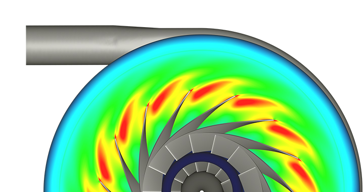
While establishing the workflow in cooperation with Teqtoniq GmbH, a test case (displayed in Figure 3 and Figure 4), was designed. This test case consists of a two-stage centrifugal compressor including a return channel and a volute. It has been developed from the ground up by means of the tools illustrated in Figure 2:
COMPAL®: A meanline design tool for centrifugal compressors. It enables designers to obtain a first estimate of stage dimensions
and performance for given boundary conditions.
AxCent®: A program for detailed geometric design and for rapid flow analysis.
OMNIS™: Final 3D CFD analysis, including geometry manipulations and meshing.
After this first step, the preliminary design was optimized with MINAMO for maximum total-total stage efficiency keeping all geometrical parameters fixed except for the blade angle distribution. Although this approach keeps the design-space relatively small, is also reduces the failure rate during geometry and mesh generation to a minimum.
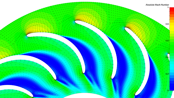
A first impression of both designs can be obtained by means of Figure 3 & Figure 4. The geometry in red represents the first draft and blue the optimized machine. While the optimizer has applied only minor changes to the first impeller, the second stage was modified significantly. The reason for this are strong flow separations in the return channel (Figure 5), which have not been predicted by the preliminary design tools. These separations are causing high incidence angles for the second stage, and thus a decrease in range and efficiency. Performance and operating characteristics for both designs will be discussed by means of Figure 6.
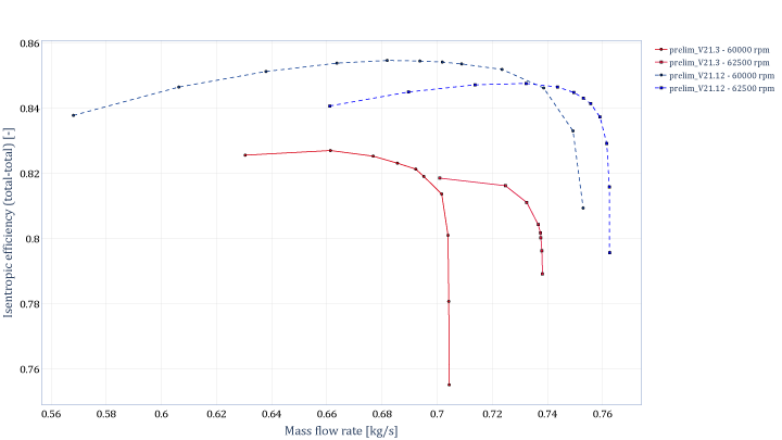
3. Preliminary vs. optimized design
This chart compares the isentropic efficiency for two designs, each represented with two speedlines over a range of flow rates. The red solid traces (labeled v21.3) represent the first geometry which was obtained after a few iterations with COMPAL® and AxCent®. Considering the complexity of the case and the very short engineering time, these results are satisfactory. However, a few optimization cycles with MINAMO lead to version v12.12 (traced with the dashed lines in blue) which outperforms v21.3 significantly in terms of both efficiency (+ 2-3 p.p) and operation range (+ 50%).
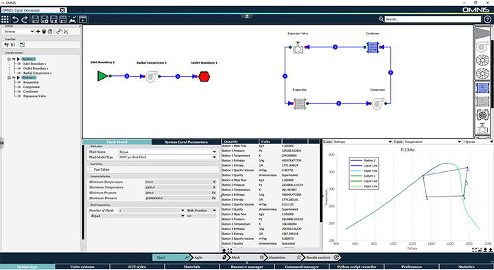
4. OMNIS-Agile – A short preview
The workflow introduced in Section 2 requires the application of three different tools (meanline-design in COMPAL®, 3D-design in AxCent®, 3D-CFD analysis in OMNIS™/Turbo). Additional tools would be required to design the cycle and to optimize the design. Here is where OMNIS™/Agile comes into play. OMNIS™/Agile, which will be available later this year, lays the foundation to conduct the entire process in one single environment. That is the user starts by designing his cycle, continues with the preliminary design of each turbomachinery component and concludes the analysis with a full 3D CFD analysis, steady and/or unsteady. A lifehack on this topic will follow at the beginning of next year.
Produkte
 Refrigerant Compressor
 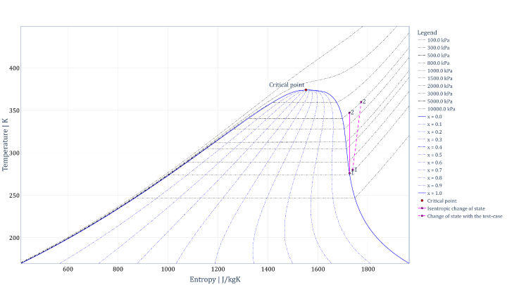 Figure 1: A temperature – entropy diagram for a refrigerant showing an example of both an idealized and a real compression of the fluid.
 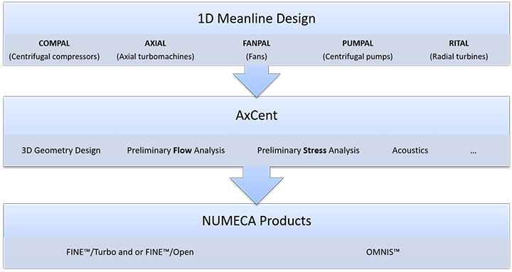 Figure 2: Product chain to design and analyze a turbomachine with the software provided by Cadence and Concepts NREC.
 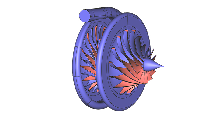 Figure 3: The test case designed during the evaluation phase with Teqtoniq – view 1. Red: Preliminary design – Blue: Optimized design.